Product Description
Introduction
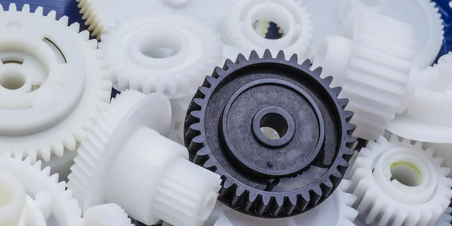
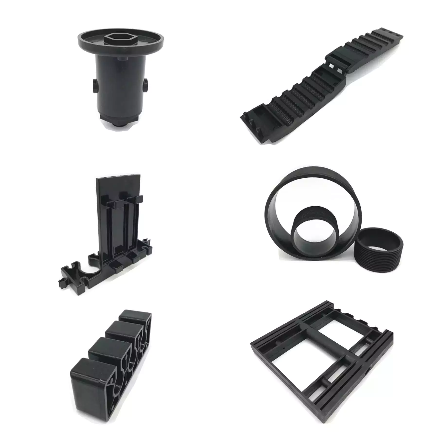
As a leading plastic injection molding company, Moldor Plastic has achieved rich experiences of design, engineering, and manufacturing value-added plastic mold and supplying molded products to customers all over the world. Equipped with state of the art machines and skilled workers, we provide you the high-quality products at very competitive price.
Our CHINAMFG are widely used in Auto Accessories, Electronics, Household appliances, Medical Devices, Game Players, Mechanical devices and other fields.
QUALITY FIRST & SERVICE FIRST & CUSTMER FIRST is our aim,MAKE EVERY PROJECT A SUCCESS is our mission.We sincerely hope to be your trustworthy partner for long-termcooperation.
Product Details
| Mold Shaping | Customized Plastic Injection Molding |
| Plastic Material | PP, PC, PS, POM, PE, ABS, etc. as per customers’ requierment |
| Surface Finish | Mirror Polish, Texture, Sandblast, Mate, Spray Paint, Silk screen and etc. |
| Plastic Material | PP, PC, PS, POM, PE, ABS, etc. as per customers’ requierment |
| Delivery Time | 5-8 days after samples confirmed |
| Color | Provide Pantone Color Code or sample |
| Packaging | Standard Export Carton |
Custom Your Own CHINAMFG in CHINAMFG !
According to your drawings or samples, we can provide one-stop solutions service from designing, prototyping, molds
making, processing, spraying, assembling, inspecting, packaging to delivering, everything will be managed to the
smallest detail.
If you have products or ideas that require injection mold & molding, CHINAMFG would like to serve you. Our knowledgeable engineers and designers will offer suggestions on how to manufacture your product to allow for a professional
look as well as for ease of manufacturing.
Please kindly email us your inquiry, and our professional team is committed to providing personal service at the
lowest possible prices to you.Your any inquiry is welcomed and will be replied soon.
1. Manufacturing experience for over 15 years.
2. Customized designs and services are accepted.
Professional design team and engineering team offer
technical support.
3. Manufacturing process control.
4. Small volume production or mass production is available.
5. Trained workers and professional QC team to assure the
product quality.
6. Inspection report and material test certificates are
available CHINAMFG requests.
7. Standard: HASCO or as customer’s requirement.
……
Step 1: Product Design: We provide product design service as customers’ request.
Step 2: Mold Design: We communicate & exchange the detail information with our customers to make a good mold design.
Step 3: Mold Making: Manufacturing in-house, we send the mold processing photos and videos to customers.
Step 4: Mass Production: We start plastic injection parts production after customers confirm samples.
Step 5: Assembly: We can supply assembly service as customers’ requests.
Step 6: Value added Service: Available, such as screen printing, plating, custom packaging and etc.
Why Us
Packaging & Shipping
FAQ
Q1:Are you a trading company or factory?
A1:We are factory.
Q2:What type of information is required for quoting a molding project?
A2:Please send your drawings or sample to us.
Q3:How long do you take to build a mold?
A3:The production timeline depends on your specific needs, normally the lead time is 25-45days.
Q4:How small or large of a plastic part will you produce?
A4:Our machine capabilities cover a range from 60-ton to 500-ton clamping forces.
Q5:What kind of steel do you use for plastic moldings?
A5:We can use any type of steel appointed by customer or popular in the market.Such as P20,718,8407,NAK80,H13,S136,
DIN 1.2738,DIN 1.2344,etc.
Q6:What types of materials can be molded by your injection products?
A6:Polystyrene,ABS,PET,TPR,TPU,PVC,Nylon,Acetal,Polypropylene,Polyethylene, Polycarbonates and etc.
Q7:Do you offer secondary service such as assembly, packaging or painting?
A7:Yes,such as assembly, painting, tapping, ultrasonic welding, trimming, sorting, customized packaging and etc.
Q8:If I have an existing tooling, could you use it to mold my project?
A8:Most certainly, if existing tooling is available, we can use them.
Q9:Can you mold around inserts or metal components?
A9:We can do insert molding with just about any metal and non-metal components.
| Plastic Type: | Thermoplastic |
|---|---|
| Plastic Form: | Granule |
| Molding Method: | Injection Molding |
| Plastic Color: | Black, Red, Yellow, White, or Others |
| Mold Runner: | Cold or Hot Runner |
| Surface Finish: | Polish, Texture, Matt, Smooth, Can Be Customized |
| Customization: |
Available
|
|
|---|
What are the typical tolerances and quality standards for injection molded parts?
When it comes to injection molded parts, the tolerances and quality standards can vary depending on several factors, including the specific application, industry requirements, and the capabilities of the injection molding process. Here are some general considerations regarding tolerances and quality standards:
Tolerances:
The tolerances for injection molded parts typically refer to the allowable deviation from the intended design dimensions. These tolerances are influenced by various factors, including the part geometry, material properties, mold design, and process capabilities. It’s important to note that achieving tighter tolerances often requires more precise tooling, tighter process control, and additional post-processing steps. Here are some common types of tolerances found in injection molding:
1. Dimensional Tolerances:
Dimensional tolerances define the acceptable range of variation for linear dimensions, such as length, width, height, and diameter. The specific tolerances depend on the part’s critical dimensions and functional requirements. Typical dimensional tolerances for injection molded parts can range from +/- 0.05 mm to +/- 0.5 mm or even tighter, depending on the complexity of the part and the process capabilities.
2. Geometric Tolerances:
Geometric tolerances specify the allowable variation in shape, form, and orientation of features on the part. These tolerances are often expressed using symbols and control the relationships between various geometric elements. Common geometric tolerances include flatness, straightness, circularity, concentricity, perpendicularity, and angularity. The specific geometric tolerances depend on the part’s design requirements and the manufacturing capabilities.
3. Surface Finish Tolerances:
Surface finish tolerances define the acceptable variation in the texture, roughness, and appearance of the part’s surfaces. The surface finish requirements are typically specified using roughness parameters, such as Ra (arithmetical average roughness) or Rz (maximum height of the roughness profile). The specific surface finish tolerances depend on the part’s aesthetic requirements, functional needs, and the material being used.
Quality Standards:
In addition to tolerances, injection molded parts are subject to various quality standards that ensure their performance, reliability, and consistency. These standards may be industry-specific or based on international standards organizations. Here are some commonly referenced quality standards for injection molded parts:
1. ISO 9001:
The ISO 9001 standard is a widely recognized quality management system that establishes criteria for the overall quality control and management of an organization. Injection molding companies often seek ISO 9001 certification to demonstrate their commitment to quality and adherence to standardized processes for design, production, and customer satisfaction.
2. ISO 13485:
ISO 13485 is a specific quality management system standard for medical devices. Injection molded parts used in the medical industry must adhere to this standard to ensure they meet the stringent quality requirements for safety, efficacy, and regulatory compliance.
3. Automotive Industry Standards:
The automotive industry has its own set of quality standards, such as ISO/TS 16949 (now IATF 16949), which focuses on the quality management system for automotive suppliers. These standards encompass requirements for product design, development, production, installation, and servicing, ensuring the quality and reliability of injection molded parts used in automobiles.
4. Industry-Specific Standards:
Various industries may have specific quality standards or guidelines that pertain to injection molded parts. For example, the aerospace industry may reference standards like AS9100, while the electronics industry may adhere to standards such as IPC-A-610 for acceptability of electronic assemblies.
It’s important to note that the specific tolerances and quality standards for injection molded parts can vary significantly depending on the application and industry requirements. Design engineers and manufacturers work together to define the appropriate tolerances and quality standards based on the functional requirements, cost considerations, and the capabilities of the injection molding process.
Are there specific considerations for choosing injection molded parts in applications with varying environmental conditions or industry standards?
Yes, there are specific considerations to keep in mind when choosing injection molded parts for applications with varying environmental conditions or industry standards. These factors play a crucial role in ensuring that the selected parts can withstand the specific operating conditions and meet the required standards. Here’s a detailed explanation of the considerations for choosing injection molded parts in such applications:
1. Material Selection:
The choice of material for injection molded parts is crucial when considering varying environmental conditions or industry standards. Different materials offer varying levels of resistance to factors such as temperature extremes, UV exposure, chemicals, moisture, or mechanical stress. Understanding the specific environmental conditions and industry requirements is essential in selecting a material that can withstand these conditions while meeting the necessary standards for performance, durability, and safety.
2. Temperature Resistance:
In applications with extreme temperature variations, it is important to choose injection molded parts that can withstand the specific temperature range. Some materials, such as engineering thermoplastics, exhibit excellent high-temperature resistance, while others may be more suitable for low-temperature environments. Consideration should also be given to the potential for thermal expansion or contraction, as it can affect the dimensional stability and overall performance of the parts.
3. Chemical Resistance:
In industries where exposure to chemicals is common, it is critical to select injection molded parts that can resist chemical attack and degradation. Different materials have varying levels of chemical resistance, and it is important to choose a material that is compatible with the specific chemicals present in the application environment. Consideration should also be given to factors such as prolonged exposure, concentration, and frequency of contact with chemicals.
4. UV Stability:
For applications exposed to outdoor environments or intense UV radiation, selecting injection molded parts with UV stability is essential. UV radiation can cause material degradation, discoloration, or loss of mechanical properties over time. Materials with UV stabilizers or additives can provide enhanced resistance to UV radiation, ensuring the longevity and performance of the parts in outdoor or UV-exposed applications.
5. Mechanical Strength and Impact Resistance:
In applications where mechanical stress or impact resistance is critical, choosing injection molded parts with the appropriate mechanical properties is important. Materials with high tensile strength, impact resistance, or toughness can ensure that the parts can withstand the required loads, vibrations, or impacts without failure. Consideration should also be given to factors such as fatigue resistance, abrasion resistance, or flexibility, depending on the specific application requirements.
6. Compliance with Industry Standards:
When selecting injection molded parts for applications governed by industry standards or regulations, it is essential to ensure that the chosen parts comply with the required standards. This includes standards for dimensions, tolerances, safety, flammability, electrical properties, or specific performance criteria. Choosing parts that are certified or tested to meet the relevant industry standards helps ensure compliance and reliability in the intended application.
7. Environmental Considerations:
In today’s environmentally conscious landscape, considering the sustainability and environmental impact of injection molded parts is increasingly important. Choosing materials that are recyclable or biodegradable can align with sustainability goals. Additionally, evaluating factors such as energy consumption during manufacturing, waste reduction, or the use of environmentally friendly manufacturing processes can contribute to environmentally responsible choices.
8. Customization and Design Flexibility:
Lastly, the design flexibility and customization options offered by injection molded parts can be advantageous in meeting specific environmental or industry requirements. Injection molding allows for intricate designs, complex geometries, and the incorporation of features such as gaskets, seals, or mounting points. Customization options for color, texture, or surface finish can also be considered to meet specific branding or aesthetic requirements.
Considering these specific considerations when choosing injection molded parts for applications with varying environmental conditions or industry standards ensures that the selected parts are well-suited for their intended use, providing optimal performance, durability, and compliance with the required standards.
Can you describe the range of materials that can be used for injection molding?
Injection molding offers a wide range of materials that can be used to produce parts with diverse properties and characteristics. The choice of material depends on the specific requirements of the application, including mechanical properties, chemical resistance, thermal stability, transparency, and cost. Here’s a description of the range of materials commonly used for injection molding:
1. Thermoplastics:
Thermoplastics are the most commonly used materials in injection molding due to their versatility, ease of processing, and recyclability. Some commonly used thermoplastics include:
- Polypropylene (PP): PP is a lightweight and flexible thermoplastic with excellent chemical resistance and low cost. It is widely used in automotive parts, packaging, consumer products, and medical devices.
- Polyethylene (PE): PE is a versatile thermoplastic with excellent impact strength and chemical resistance. It is used in various applications, including packaging, pipes, automotive components, and toys.
- Polystyrene (PS): PS is a rigid and transparent thermoplastic with good dimensional stability. It is commonly used in packaging, consumer goods, and disposable products.
- Polycarbonate (PC): PC is a transparent and impact-resistant thermoplastic with high heat resistance. It finds applications in automotive parts, electronic components, and optical lenses.
- Acrylonitrile Butadiene Styrene (ABS): ABS is a versatile thermoplastic with a good balance of strength, impact resistance, and heat resistance. It is commonly used in automotive parts, electronic enclosures, and consumer products.
- Polyvinyl Chloride (PVC): PVC is a durable and flame-resistant thermoplastic with good chemical resistance. It is used in a wide range of applications, including construction, electrical insulation, and medical tubing.
- Polyethylene Terephthalate (PET): PET is a strong and lightweight thermoplastic with excellent clarity and barrier properties. It is commonly used in packaging, beverage bottles, and textile fibers.
2. Engineering Plastics:
Engineering plastics offer enhanced mechanical properties, heat resistance, and dimensional stability compared to commodity thermoplastics. Some commonly used engineering plastics in injection molding include:
- Polyamide (PA/Nylon): Nylon is a strong and durable engineering plastic with excellent wear resistance and low friction properties. It is used in automotive components, electrical connectors, and industrial applications.
- Polycarbonate (PC): PC, mentioned earlier, is also considered an engineering plastic due to its exceptional impact resistance and high-temperature performance.
- Polyoxymethylene (POM/Acetal): POM is a high-strength engineering plastic with low friction and excellent dimensional stability. It finds applications in gears, bearings, and precision mechanical components.
- Polyphenylene Sulfide (PPS): PPS is a high-performance engineering plastic with excellent chemical resistance and thermal stability. It is used in electrical and electronic components, automotive parts, and industrial applications.
- Polyetheretherketone (PEEK): PEEK is a high-performance engineering plastic with exceptional heat resistance, chemical resistance, and mechanical properties. It is commonly used in aerospace, medical, and industrial applications.
3. Thermosetting Plastics:
Thermosetting plastics undergo a chemical crosslinking process during molding, resulting in a rigid and heat-resistant material. Some commonly used thermosetting plastics in injection molding include:
- Epoxy: Epoxy resins offer excellent chemical resistance and mechanical properties. They are commonly used in electrical components, adhesives, and coatings.
- Phenolic: Phenolic resins are known for their excellent heat resistance and electrical insulation properties. They find applications in electrical switches, automotive parts, and consumer goods.
- Urea-formaldehyde (UF) and Melamine-formaldehyde (MF): UF and MF resins are used for molding electrical components, kitchenware, and decorative laminates.
4. Elastomers:
Elastomers, also known as rubber-like materials, are used to produce flexible and elastic parts. They provide excellent resilience, durability, and sealing properties. Some commonly used elastomers in injection molding include:
- Thermoplastic Elastomers (TPE): TPEs are a class of materials that combine the characteristics of rubber and plastic. They offer flexibility, good compression set, and ease of processing. TPEs find applications in automotive components, consumer products, and medical devices.
- Silicone: Silicone elastomers provide excellent heat resistance, electrical insulation, and biocompatibility. They are commonly used in medical devices, automotive seals, and household products.
- Styrene Butadiene Rubber (SBR): SBR is a synthetic elastomer with good abrasion resistance and low-temperature flexibility. It is used in tires, gaskets, and conveyor belts.
- Ethylene Propylene Diene Monomer (EPDM): EPDM is a durable elastomer with excellent weather resistance and chemical resistance. It finds applications in automotive seals, weatherstripping, and roofing membranes.
5. Composites:
Injection molding can also be used to produce parts made of composite materials, which combine two or more different types of materials to achieve specific properties. Commonly used composite materials in injection molding include:
- Glass-Fiber Reinforced Plastics (GFRP): GFRP combines glass fibers with thermoplastics or thermosetting resins to enhance mechanical strength, stiffness, and dimensional stability. It is used in automotive components, electrical enclosures, and sporting goods.
- Carbon-Fiber Reinforced Plastics (CFRP): CFRP combines carbon fibers with thermosetting resins to produce parts with exceptional strength, stiffness, and lightweight properties. It is commonly used in aerospace, automotive, and high-performance sports equipment.
- Metal-Filled Plastics: Metal-filled plastics incorporate metal particles or fibers into thermoplastics to achieve properties such as conductivity, electromagnetic shielding, or enhanced weight and feel. They are used in electrical connectors, automotive components, and consumer electronics.
These are just a few examples of the materials used in injection molding. There are numerous other specialized materials available, each with its own unique properties, such as flame retardancy, low friction, chemical resistance, or specific certifications for medical or food-contact applications. The selection of the material depends on the desired performance, cost considerations, and regulatory requirements of the specific application.


editor by CX 2023-12-06
China Custom custom high quality smooth surface no glitch ABS Plastic worm gear box injection molding plastic parts manufacturer
Model Number: TG-A12
Plastic Modling Type: injection
Processing Service: Moulding, Cutting
OEM Service: Support
Tolerance: 0.01-0.05mm or Customized
Certification: ISO9001,
Surface Treatment: Sandblasting,Polishing,Anodize, Zinc,Nickel,Chrome,Plating, etc.
Application: Automobile,Medical Equipments,Electric Appliance,Hardware,etc.
Dimension: As Customers’ Request
Equipment: Milling/Lathe/Drilling/Four/Three Axis CNC Machining Center
Drawing Format: PRO/E, Auto CAD, Solid Works,IGS,UG, CAD/CAM/CAE
MOQ: 100
Material: ABS
Packaging Details: High precision plastic and metal 1,With plastic bag,with pearl-cotton package. 2,To be packed in cartons. 3,Use glues tape to seal cartons. 4,Deliver out by DHL,FEDEX. Or according to customers’ requirement.
Port: HangZhou, ZheJiang
| Product Name | Factory manufacture Customized precision 5 axis cnc machining plastic injection molding parts |
| Product Type | CNC turning, milling, drilling, grinding, wire EDM cutting etc. |
| Our Services | CNC Machining,Plastic Injection,Stamping,Die Casting,Silicone And Rubber,Aluminum Extrusion,Mould Making,etc |
| Material | Aluminum,Brass,Stainless Steel,Copper,Plastic,Wood,Silicone,Rubber,Or as per the customers’ requirements |
| Surface Treatment | Anodizing,Sandblasting,Painting,Powder coating,Plating,Silk Printing,Brushing,Polishing,Laser Engraving |
| Dimension | As customers’ request |
| Service Project | To provide production design, production and technical service, CZPT development and processing, etc |
| Drawing Format | PRO/E, Auto CAD, Solid Works,IGS,UG, CAD/CAM/CAE |
| Testing Machine | Digital Height Gauge, caliper, Coordinate measuring machine, projection machine, roughness tester, hardness tester and so on |
| Industry used | Machinery; heavy duty equipment; electronic device; Auto spare parts; optical telecommunication |
| Packing | Eco-friendly pp bag / EPE Foam /Carton boxes or wooden boxes As customer’s specific requirements |
| Trial sample time | 7-10 days after confirmation |
| Delivery time | 7-30 days after receive the pre-payments |
| Payment Terms | T/T,Western Union,Paypal |
Benefits of Injection Molded Parts in Design
Injection molded parts are manufactured from a variety of plastics. You can order samples of your desired product or download CAD drawings free of charge. For more information, visit our product catalog. There are numerous benefits of using injection molded products in your designs. Here are some of them. Injection molded products are cost-effective and highly customizable.
Design for manufacturability
 Design for manufacturability (DFMA) is an important part of the design process for injection-molded parts. This process helps to minimize costs and streamline the production process. It also helps in the prevention of problems during the manufacturing process. The process involves several steps that include part geometry, location of critical surfaces, material selection, and dimensioning. It is also crucial to consider the colors and tolerances, which can help to minimize scrap rates.
Design for manufacturability is a vital early stage in the development process to ensure that the product is cost-effective and repeatable. It begins with a thorough understanding of the purpose for which the part is intended. The design process should take into account every aspect of the part, including the material section, tool design, and the production process.
DFM includes guidelines to ensure that the design meets the manufacturing requirements. These guidelines can include good manufacturing practices, as well as good design principles. Good design focuses on the quantity and quality of parts, as well as the complexity of their surfaces and tolerances. The process also focuses on mechanical and optical properties.
Injection molding design for manufacturability can save resources and time. It also reduces the costs of assembly. An injection molder conducts a detailed analysis of these design elements before starting the tooling process. This is not a standalone principle; it should be used in conjunction with other design optimization techniques.
Ideally, a product should be designed for optimum manufacture. This means that it should not have too many parts, or too few. To minimize this, the designer should choose a model that is easy to mold. Also, a design that does not require too many machine operations and minimizes risks.
Plastics used in injection molding
 Injection molding is a very versatile process that uses various types of plastic polymers. These plastics are extremely flexible and can be molded to take on any shape, color, and finish. They can also be customized to contain design elements, text, and safety instructions. Plastics are also lightweight, easily recycled, and can be hermetically sealed to prevent moisture from getting into the product.
Plastics are categorized according to their properties, which can be helpful in selecting the right plastic for a particular application. Different materials have different degrees of hardness, which is important when it comes to molding applications. Some are harder than others, while others are more flexible. Plastics are ranked according to their Shore hardness, which was developed by CZPT.
Polystyrene is one of the most common plastics used in injection molding. However, it has a few disadvantages. While it is a good choice for simple products that do not require high strength and are prone to breakage, it is not ideal for items that need to be resistant to heat and pressure.
While many types of plastics are used in injection molding, choosing the right material is very important. The right material can make a big difference in the performance of your product and the cost of your product. Make sure to talk with your injection molding supplier to determine which plastic is right for your project. You should look for a plastic with a high impact rating and FDA approval.
Another commonly used plastic is PMMA, or polystyrene. This plastic is affordable and has a glass-like finish. It is often used for food and beverage packaging and can be easily recycled. This material is also used in textiles.Characteristics of polypropylene
Polypropylene injection molded parts offer an array of benefits, including a high degree of rigidity, excellent thermal stability, low coefficient of friction, and chemical resistance. These plastics are available in two main types, homopolymers and copolymers. Both types offer superior hardness and tensile strength. However, the material does not have the same fire-resistance as PE plastics.
Polypropylene is a colorless, odorless, crystalline solid. It is highly resistant to a variety of chemicals and is shatter-resistant. Its properties make it a great choice for many industrial applications, including packaging and containers for liquids. The material is also highly durable and can last for a very long time without breaking. In addition, it does not absorb or retain moisture, making it ideal for outdoor and laboratory applications.
Polypropylene is widely used for injection molding, and its low cost, flexibility, and resistance to chemical attack make it a popular choice. This material is also a great electrical insulator and has excellent thermal expansion coefficient. However, it is not biodegradable. Luckily, it can be recycled.
During the molding process, the temperature of the mold is a significant factor. Its morphology is related to the temperature and flow field, and a clear correlation between the two factors is essential. If you can control the temperature and flow, you can optimize your manufacturing process and eliminate costly trial-and-error procedures.
Polypropylene is an excellent electrical insulator and has a high dielectric coefficient. It can also be sterilized and resist high temperatures. Although it is less rigid than polyethylene, it is a good choice for applications where electrical insulation is necessary.
Texture of injection molded parts
 Texture design is a common feature of injection molded parts, which helps to raise the perceived value of the vehicle. While traditional manufacturing processes can produce limited textures, additive manufacturing allows for infinite designs. For example, a design that looks like a wood grain pattern may be printed on an aluminum car part.
Texture is important because it can improve the strength of the part and enhance its adhesion to other surfaces. Moreover, textured parts can resist damage from contact and fingerprints. This makes them more durable and a good option for further molding operations. Injection molding processes usually follow a set of standards from the Society of Plastics Industry, which define different types of surface finishes.
Textured plastic injection molded parts may have various types of surfaces, including wood grain, leather, sand, or stipple. Choosing the right surface texture is crucial for enhancing the appearance of the part, but it must also be compatible with its function. Different materials have different chemical and physical properties, which can influence the type of texture. Moreover, the melting temperature of the material is important for its surface finish. The additives used in the process can also have an impact on the surface finish.
Texture can also vary between manufacturers and types of components. Some textures are flat, while others are rough. The top row corresponds to A3 and B4 in flatness, while the bottom row shows rough surfaces. These rough surfaces may damage sensitive testing equipment. However, some textures may have near equivalence with each other, namely SPI D-3 and MT-11020.
The type of texture that is applied to injection molded parts can affect the minimum draft angle required for the parts to be ejected. Parts with light texture tend to be smoother than parts with heavy textures, while parts with heavy textures require a higher draft angle. The draft angle for heavy textures should be between five and 12 degrees. It is best to consider this early in the design process and consult with the injection molder to get a good idea of the necessary draft angles.
editor by czh
China Standard High Quality Plastic Non Actuator Butterfly Valve PVC Wafer Type Butterfly Valve Lever UPVC Worm Gear EPDM FPM Nr Butterfly Valve DIN ANSI JIS Standard with Free Design Custom
Item Description
High Top quality
Plastic Non Actuator Butterfly Valve
PVC Wafer Sort Butterfly Valve Lever
UPVC Worm Gear EPDM FPM NR Butterfly Valve
DIN ANSI JIS Common
DIN ANSI JIS Regular
DN50-DN400 ( 2″-16″ )
High Quality
Plastic Non Actuator Butterfly Valve
PVC Wafer Butterfly Valve Level
UPVC Worm Equipment Butterfly Valves for Swimming Pool
DIN ANSI JIS Normal
With Carbon Steel Stem #forty five. Disc with PVC. Seat & O-Ring with EPDM Rubber.
With Stainless Steel Stem # 304. Disc with PVC. Seat & O-Ring with EPDM Rubber
With Stainless Metal Stem # 316. Disc with PVC. Seat & O-Ring with EPDM Rubber
With Stainless Metal Stem # 304. Disc with PVC. Seat & O-Ring with FPM Rubber
With Stainless Steel Stem #316. Disc with PVC Seat & O-Ring with FPM Rubber
Substantial Quality
PVC Butterfly Valve DIN, ANSI, JIS Standard
DN50-DN400 ( 2″-16″ )
Attributes
Water Supply
Material : PVC-U
Standard : DIN ANSI JIS Regular
Connection : Flange
SIZE : DN50 ( 63mm ) 2″ ~ DN400 (400mm ) 16″
Working Pressure : 150PSI 1.0 MPa
100PSI 0.6MPa
Color : Dark Grey
PVC Butterfly Valve ( Stage & Gear )
FRPP Butterfly Valve ( Stage & Gear )
PVC Non Actuator Butterfly Valve for Electric powered & Pneumatic Actuator Use
PVC-U FRPP Butterfly Valve for Electric powered & Pneumatic Actuator Utilization
DN50-DNfour00 ( 2″- onesix” )
DN50 – DN150 (2″- 6″) 100PSI PN0.8MPa
DN200-DN300 (8″- twelve”) 80PSI PN0.5MPa
DN350-DN400 (fourteen”- 16″) 60PSI PN0.4MPa
Standard: DIN, ANSI, JIS Common
Hello-Quality Low Torque Acid-Proof Alkali-Proof 100% Test
Can be Tailored
Distinct Dimensions Shaft of Sq., Oblate, Round Keyway
Large the Valve Human body, Thicken the Valve Plate
Thicken the Valve Stem, the Valve Stem Limit
With Carbon Metal Stem #45 & EPDM Rubber
With Stainless Metal Stem #304 & EPDM / FPM Rubber
With Stainless Steel Stem #316 & EPDM / FPM Rubber
Built-in Construction of Valve Seat and Valve Body
Actuator Mounting Gap
with ISO5211 Standard Without Bracket, Direct Connection
PVC-U FRPP Butterfly Valve ( Lever Type ) DN50-DN200 ( 2″- 8″ )
Working Stress:
DN50-DN150 ( 2″- 6″ ) 150PSI PN1.0MPa
DN200 ( 8″ ) 90PSI PN0.6MPa
Normal: DIN, ANSI, JIS Regular
Hello-Top quality, Low Torque, Lockable, Acid-Evidence, Alkali-Evidence, a hundred% Examination
PVC Butterfly Valve Patent Technological innovation
Increase the Locking Gap to Lock the Valve
Integrated Composition of Valve Seat and Valve Physique.
Large the Valve Entire body, Thicken the Valve Plate
Thicken the Valve Stem, the Valve Stem Restrict
With Carbon Steel Stem #45 & EPDM Rubber
With Stainless Steel Stem #304 & EPDM / FPM Rubber
With Stainless Steel Stem #316 & EPDM / FPM Rubber
For a longer time & Wider Handle,Take care of Lever Bigger, Work Operation
PVC-U FRPP Butterfly Valve ( Equipment Kind ) DN50-DN400 ( 2″- sixteen” )
DN50-DN200 (2″- 8″) 150PSI PN1.0MPa
DN250-DN300 (10″- twelve”) 90PSI PN0.6MPa
DN350-DN400 (14″- sixteen”) 60PSI PN0.4MPa
Standard: DIN, ANSI, JIS Normal
Hello-Quality Low Torque Acid-Evidence Alkali-Evidence 100% Test
Hygienic Stage PVC Uncooked Materials Injection
Equipment Box and Hand Wheel Can Be Created of Plastic
Integrated Composition of Valve Seat and Valve Entire body
With Carbon Metal Stem #forty five & EPDM Rubber
With Stainless Steel Stem #304 & EPDM / FPM Rubber
With Stainless Steel Stem #316 & EPDM / FPM Rubber
What Are Worm Gears and Worm Shafts?
If you might be looking for a fishing reel with a worm gear system, you’ve got possibly arrive throughout the phrase ‘worm gear’. But what are worm gears and worm shafts? And what are the positive aspects and negatives of worm gears? Let us just take a closer look! Go through on to understand more about worm gears and shafts! Then you will be well on your way to getting a reel with a worm equipment method.
worm equipment reducers
Worm shaft reducers have a number of benefits above conventional gear reduction mechanisms. 1st, they’re extremely successful. While one stage worm reducers have a greatest reduction ratio of about 5 to sixty, hypoid gears can normally go up to a highest of one hundred and 20 times. A worm shaft reducer is only as effective as the gearing it makes use of. This article will discuss some of the advantages of utilizing a hypoid gear established, and how it can benefit your enterprise.
To assemble a worm shaft reducer, initial eliminate the flange from the motor. Then, remove the output bearing carrier and output equipment assembly. And lastly, put in the intermediate worm assembly by way of the bore opposite to the attachment housing. Once set up, you must carefully get rid of the bearing provider and the equipment assembly from the motor. Do not neglect to take away the oil seal from the housing and motor flange. For the duration of this method, you should use a modest hammer to tap around the face of the plug near the outside diameter of the housing.
Worm gears are usually utilised in reversing prevention systems. The backlash of a worm equipment can increase with wear. Nonetheless, a duplex worm equipment was developed to deal with this dilemma. This kind of equipment requires a smaller backlash but is still highly specific. It employs diverse sales opportunities for the opposing tooth confront, which continually alters its tooth thickness. Worm gears can also be modified axially.
worm gears
There are a pair of diverse sorts of lubricants that are utilised in worm gears. The 1st, polyalkylene glycols, are used in instances the place substantial temperature is not a problem. This variety of lubricant does not include any waxes, which helps make it an exceptional selection in lower-temperature programs. However, these lubricants are not compatible with mineral oils or some kinds of paints and seals. Worm gears usually characteristic a metal worm and a brass wheel. The brass wheel is much easier to remodel than metal and is generally modeled as a sacrificial ingredient.
The worm equipment is most powerful when it is utilized in small and compact applications. Worm gears can greatly boost torque or decrease speed, and they are typically utilized where room is an issue. Worm gears are between the smoothest and quietest equipment techniques on the market place, and their meshing usefulness is superb. Nevertheless, the worm equipment requires large-top quality producing to perform at its optimum stages. If you are contemplating a worm equipment for a task, it is crucial to make sure that you locate a manufacturer with a extended and large top quality reputation.
The pitch diameters of each worm and pinion gears should match. The two worm cylinders in a worm wheel have the exact same pitch diameter. The worm wheel shaft has two pitch cylinders and two threads. They are similar in pitch diameter, but have diverse advancing angles. A self-locking worm gear, also identified as a wormwheel, is typically self-locking. In addition, self-locking worm gears are straightforward to install.
worm shafts
The deflection of worm shafts varies with toothing parameters. In addition to toothing duration, worm gear size and strain angle, worm equipment measurement and amount of helical threads are all influencing variables. These versions are modeled in the common ISO/TS 14521 reference equipment. This table shows the variants in each and every parameter. The ID implies the worm shaft’s heart length. In addition, a new calculation technique is presented for identifying the equal bending diameter of the worm.
The deflection of worm shafts is investigated utilizing a 4-stage approach. Very first, the finite factor approach is utilized to compute the deflection of a worm shaft. Then, the worm shaft is experimentally tested, evaluating the final results with the corresponding simulations. The ultimate stage of the simulation is to think about the toothing geometry of fifteen diverse worm equipment toothings. The final results of this action verify the modeled outcomes.
The direct on the right and left tooth surfaces of worms is the exact same. Nonetheless, the direct can be varied together the worm shaft. This is referred to as twin lead worm equipment, and is utilized to eliminate enjoy in the principal worm equipment of hobbing equipment. The pitch diameters of worm modules are equivalent. The exact same basic principle applies to their pitch diameters. Usually, the lead angle increases as the number of threads decreases. Hence, the larger the guide angle, the much less self-locking it gets.
worm gears in fishing reels
Fishing reels typically include worm shafts as a element of the construction. Worm shafts in fishing reels allow for uniform worm winding. The worm shaft is connected to a bearing on the rear wall of the reel unit by means of a hole. The worm shaft’s entrance end is supported by a concave hole in the front of the reel unit. A traditional fishing reel might also have a worm shaft attached to the sidewall.
The equipment help part 29 supports the rear conclude of the pinion equipment twelve. It is a thick rib that protrudes from the lid part 2 b. It is mounted on a bushing fourteen b, which has a via hole by way of which the worm shaft twenty passes. This worm equipment supports the worm. There are two types of worm gears offered for fishing reels. The two kinds of worm gears might have distinct quantity of tooth or they could be the exact same.
Common worm shafts are manufactured of stainless steel. Stainless metal worm shafts are especially corrosion-resistant and tough. Worm shafts are utilised on spinning reels, spin-casting reels, and in a lot of electrical equipment. A worm shaft can be reversible, but it is not entirely reputable. There are quite a few benefits of worm shafts in fishing reels. These fishing reels also feature a line winder or amount winder.
worm gears in electrical tools
Worms have various tooth shapes that can aid increase the load carrying potential of a worm gear. Distinct tooth designs can be used with circular or secondary curve cross sections. The pitch point of the cross part is the boundary for this variety of mesh. The mesh can be both constructive or negative based on the preferred torque. Worm enamel can also be inspected by measuring them in excess of pins. In a lot of situations, the direct thickness of a worm can be modified making use of a gear tooth caliper.
The worm shaft is mounted to the reduced situation segment 8 by means of a rubber bush thirteen. The worm wheel 3 is connected to the joint shaft 12. The worm 2 is coaxially attached to the shaft end segment 12a. This joint shaft connects to a swing arm and rotates the worm wheel 3.
The backlash of a worm equipment may be elevated if the worm is not mounted appropriately. To resolve the problem, manufacturers have produced duplex worm gears, which are appropriate for modest backlash apps. Duplex worm gears employ distinct sales opportunities on each and every tooth experience for ongoing alter in tooth thickness. In this way, the heart length of the worm gear can be altered without having altering the worm’s design.
worm gears in engines
Utilizing worm shafts in engines has a handful of positive aspects. 1st of all, worm gears are tranquil. The equipment and worm experience shift in opposite directions so the strength transferred is linear. Worm gears are common in programs the place torque is important, these kinds of as elevators and lifts. Worm gears also have the gain of being manufactured from comfortable components, creating them simple to lubricate and to use in apps where noise is a problem.
Lubricants are essential for worm gears. The viscosity of lubricants determines regardless of whether the worm is capable to touch the gear or wheel. Widespread lubricants are ISO 680 and 460, but higher viscosity oil is not unheard of. It is crucial to use the correct lubricants for worm gears, given that they can’t be lubricated indefinitely.
Worm gears are not advised for engines owing to their limited performance. The worm gear’s spiral motion leads to a considerable reduction in room, but this demands a higher sum of lubrication. Worm gears are inclined to breaking down due to the fact of the anxiety placed on them. Additionally, their constrained pace can trigger significant hurt to the gearbox, so watchful servicing is important. To make certain worm gears remain in leading situation, you must inspect and clean them routinely.
Approaches for manufacturing worm shafts
A novel technique to production worm shafts and gearboxes is supplied by the methods of the existing invention. Factors of the technique include manufacturing the worm shaft from a typical worm shaft blank obtaining a defined outer diameter and axial pitch. The worm shaft blank is then adapted to the preferred gear ratio, resulting in a gearbox loved ones with a number of gear ratios. The preferred technique for production worm shafts and gearboxes is outlined below.
A worm shaft assembly process may involve creating an axial pitch for a given frame dimension and reduction ratio. A one worm shaft blank normally has an outer diameter of one hundred millimeters, which is the measurement of the worm equipment set’s middle length. Upon completion of the assembly procedure, the worm shaft has the sought after axial pitch. Methods for producing worm shafts incorporate the subsequent:
For the layout of the worm equipment, a large diploma of conformity is necessary. Worm gears are categorized as a screw pair in the lower pairs. Worm gears have higher relative sliding, which is advantageous when comparing them to other sorts of gears. Worm gears need very good area finish and rigid positioning. Worm equipment lubrication normally includes surface lively additives this kind of as silica or phosphor-bronze. Worm equipment lubricants are often mixed. The lubricant film that kinds on the equipment enamel has tiny effect on put on and is usually a excellent lubricant.


China factory High Quality Plastic Wafer Type Lug EPDM Manual Handle Seal Butterfly Valve UPVC Worm Gear Flange Butterfly Valve PVC FPM Seat Butterfly Valve with Great quality
Solution Description
Large Top quality
Plastic Wafer Kind Lug EPDM Manual Seal Butterfly Valve
UPVC Worm Equipment Flange Butterfly Valve
PVC FPM Seat Manage Butterfly Valve
DIN ANSI JIS Normal
DN50-DN400 ( Dia.63-Dia.four hundred )
Higher Good quality
Plastic Wafer Butterfly Valve
DIN ANSI JIS Common
UPVC Worm Gear Butterfly Valve
PVC Butterfly Valve
DN50 / Dia.63mm – DN400 / Dia.400mm
PVC Butterfly Valve ( Lever & Equipment )
FRPP Butterfly Valve ( Lever & Gear )
PVC Non Actuator Butterfly Valve for Electrical & Pneumatic Actuator Utilization
Large Top quality
PVC Butterfly Valve for Drinking water Supply DIN ANSI JIS Standard
DN.50mm to DN.400mm
Features
Water Supply
Material : PVC-U
Standard : DIN ANSI JIS Standard
Connection : Flange
SIZE : DN50 ( 63mm ) 2″ ~ DN400 (400mm ) sixteen”
Working Pressure : 150PSI one.0 MPa
100PSI 0.6MPa
Color : Darkish Gray
With Carbon Metal Stem #45. Disc with PVC. Seat & O-Ring with EPDM Rubber.
With Stainless Steel Stem # 304. Disc with PVC. Seat & O-Ring with EPDM Rubber
With Stainless Metal Stem # 316. Disc with PVC. Seat & O-Ring with EPDM Rubber
With Stainless Steel Stem # 304. Disc with PVC. Seat & O-Ring with FPM Rubber
With Stainless Metal Stem #316. Disc with PVC Seat & O-Ring with FPM Rubber.
PVC-U FRPP Butterfly Valve for Electric powered & Pneumatic Actuator Usage
DN50-DNfour00 ( 2″- one6” )
DN50 – DN150 (2″- 6″) 100PSI PN0.8MPa
DN200-DN300 (8″- twelve”) 80PSI PN0.5MPa
DN350-DN400 (fourteen”- sixteen”) 60PSI PN0.4MPa
Standard: DIN, ANSI, JIS Normal
Hello-Good quality Low Torque Acid-Evidence Alkali-Evidence 100% Examination
Can be Custom-made
Distinct Sizes Shaft of Square, Oblate, Spherical Keyway
Weighty the Valve Body, Thicken the Valve Plate
Thicken the Valve Stem, the Valve Stem Limit
With Carbon Metal Stem #forty five & EPDM Rubber
With Stainless Steel Stem #304 & EPDM / FPM Rubber
With Stainless Steel Stem #316 & EPDM / FPM Rubber
Built-in Composition of Valve Seat and Valve Physique
Actuator Mounting Gap
with ISO5211 Regular With out Bracket, Immediate Link
PVC-U FRPP Butterfly Valve ( Lever Kind ) DN50-DN200 ( 2″- 8″ )
Doing work Strain:
DN50-DN150 ( 2″- 6″ ) 150PSI PN1.0MPa
DN200 ( 8″ ) 90PSI PN0.6MPa
Common: DIN, ANSI, JIS Normal
Hi-Top quality, Reduced Torque, Lockable, Acid-Proof, Alkali-Proof, a hundred% Check
PVC Butterfly Valve Patent Technology
Increase the Locking Hole to Lock the Valve
Built-in Framework of Valve Seat and Valve Human body.
Hefty the Valve Entire body, Thicken the Valve Plate
Thicken the Valve Stem, the Valve Stem Limit
With Carbon Steel Stem #forty five & EPDM Rubber
With Stainless Metal Stem #304 & EPDM / FPM Rubber
With Stainless Metal Stem #316 & EPDM / FPM Rubber
Lengthier & Broader Take care of,Take care of Lever Larger, Effort Operation
PVC-U FRPP Butterfly Valve ( Gear Kind ) DN50-DN400 ( 2″- 16″ )
DN50-DN200 (2″- 8″) 150PSI PN1.0MPa
DN250-DN300 (ten”- twelve”) 90PSI PN0.6MPa
DN350-DN400 (14″- 16″) 60PSI PN0.4MPa
Normal: DIN, ANSI, JIS Regular
Hi-High quality Low Torque Acid-Proof Alkali-Proof 100% Test
Hygienic Level PVC Raw Content Injection
Gear Box and Hand Wheel Can Be Manufactured of Plastic
Built-in Structure of Valve Seat and Valve Entire body
With Carbon Metal Stem #forty five & EPDM Rubber
With Stainless Steel Stem #304 & EPDM / FPM Rubber
With Stainless Steel Stem #316 & EPDM / FPM Rubber
An Overview of Worm Shafts and Gears
This article provides an overview of worm shafts and gears, such as the kind of toothing and deflection they experience. Other topics coated contain the use of aluminum as opposed to bronze worm shafts, calculating worm shaft deflection and lubrication. A comprehensive comprehension of these troubles will help you to layout greater gearboxes and other worm gear mechanisms. For more data, you should check out the relevant sites. We also hope that you will discover this post educational.
Double throat worm gears
The pitch diameter of a worm and the pitch of its worm wheel need to be equivalent. The two kinds of worm gears have the very same pitch diameter, but the distinction lies in their axial and round pitches. The pitch diameter is the length in between the worm’s tooth alongside its axis and the pitch diameter of the more substantial equipment. Worms are manufactured with remaining-handed or correct-handed threads. The direct of the worm is the length a stage on the thread travels for the duration of a single revolution of the worm equipment. The backlash measurement ought to be produced in a couple of various areas on the equipment wheel, as a large quantity of backlash implies tooth spacing.
A double-throat worm equipment is developed for substantial-load apps. It offers the tightest link between worm and gear. It is essential to mount a worm equipment assembly properly. The keyway style needs a number of factors of make contact with, which block shaft rotation and support transfer torque to the gear. After deciding the spot of the keyway, a gap is drilled into the hub, which is then screwed into the gear.
The twin-threaded style of worm gears makes it possible for them to stand up to large hundreds with no slipping or tearing out of the worm. A double-throat worm gear supplies the tightest connection amongst worm and gear, and is consequently best for hoisting applications. The self-locking character of the worm gear is another edge. If the worm gears are made properly, they are superb for reducing speeds, as they are self-locking.
When deciding on a worm, the variety of threads that a worm has is crucial. Thread commences establish the reduction ratio of a pair, so the larger the threads, the better the ratio. The exact same is accurate for the worm helix angles, which can be 1, two, or 3 threads long. This varies in between a single thread and a double-throat worm gear, and it is vital to contemplate the helix angle when selecting a worm.
Double-throat worm gears differ in their profile from the real gear. Double-throat worm gears are particularly useful in programs exactly where noise is an situation. In addition to their lower sounds, worm gears can take up shock masses. A double-throat worm gear is also a well-known decision for many different varieties of programs. These gears are also frequently employed for hoisting products. Its tooth profile is diverse from that of the actual equipment.
Bronze or aluminum worm shafts
When choosing a worm, a couple of factors should be stored in head. The material of the shaft need to be either bronze or aluminum. The worm alone is the primary part, but there are also addendum gears that are offered. The whole number of enamel on equally the worm and the addendum equipment ought to be better than forty. The axial pitch of the worm requirements to match the circular pitch of the bigger equipment.
The most typical content employed for worm gears is bronze since of its fascinating mechanical houses. Bronze is a broad term referring to various copper alloys, like copper-nickel and copper-aluminum. Bronze is most commonly developed by alloying copper with tin and aluminum. In some situations, this mix results in brass, which is a comparable metal to bronze. The latter is less expensive and appropriate for gentle masses.
There are numerous rewards to bronze worm gears. They are sturdy and durable, and they offer outstanding dress in-resistance. In contrast to metal worms, bronze worm gears are quieter than their counterparts. They also demand no lubrication and are corrosion-resistant. Bronze worms are well-liked with small, gentle-excess weight equipment, as they are easy to maintain. You can read far more about worm gears in CZPT’s CZPT.
Even though bronze or aluminum worm shafts are the most frequent, both materials are equally suitable for a selection of applications. A bronze shaft is usually called bronze but might actually be brass. Historically, worm gears ended up produced of SAE 65 gear bronze. Even so, newer supplies have been launched. SAE 65 equipment bronze (UNS C90700) stays the preferred content. For high-quantity programs, the materials financial savings can be significant.
Both sorts of worms are basically the identical in size and form, but the lead on the still left and proper tooth surfaces can differ. This permits for exact adjustment of the backlash on a worm without having altering the heart distance in between the worm gear. The different dimensions of worms also make them simpler to manufacture and sustain. But if you want an specially little worm for an industrial software, you should think about bronze or aluminum.
Calculation of worm shaft deflection
The centre-line distance of a worm equipment and the quantity of worm enamel enjoy a crucial function in the deflection of the rotor. These parameters need to be entered into the device in the same models as the primary calculation. The chosen variant is then transferred to the main calculation. The deflection of the worm equipment can be calculated from the angle at which the worm tooth shrink. The subsequent calculation is beneficial for creating a worm gear.
Worm gears are commonly utilised in industrial programs thanks to their large transmittable torques and huge gear ratios. Their hard/soft content blend tends to make them ideally suited for a wide range of applications. The worm shaft is normally made of situation-hardened metal, and the worm wheel is fabricated from a copper-tin-bronze alloy. In most cases, the wheel is the spot of speak to with the gear. Worm gears also have a reduced deflection, as high shaft deflection can impact the transmission precision and increase put on.
Yet another approach for determining worm shaft deflection is to use the tooth-dependent bending stiffness of a worm gear’s toothing. By calculating the stiffness of the personal sections of a worm shaft, the stiffness of the total worm can be decided. The approximate tooth region is demonstrated in figure 5.
Yet another way to determine worm shaft deflection is by utilizing the FEM strategy. The simulation instrument employs an analytical model of the worm equipment shaft to figure out the deflection of the worm. It is primarily based on a two-dimensional model, which is a lot more appropriate for simulation. Then, you require to enter the worm gear’s pitch angle and the toothing to compute the greatest deflection.
Lubrication of worm shafts
In order to shield the gears, worm drives demand lubricants that provide outstanding anti-dress in safety, substantial oxidation resistance, and reduced friction. Whilst mineral oil lubricants are commonly utilised, synthetic foundation oils have better efficiency attributes and decrease working temperatures. The Arrhenius Charge Rule states that chemical reactions double every single ten levels C. Synthetic lubricants are the best option for these programs.
Synthetics and compounded mineral oils are the most common lubricants for worm gears. These oils are formulated with mineral basestock and 4 to six per cent artificial fatty acid. Surface area-energetic additives give compounded equipment oils fantastic lubricity and avoid sliding dress in. These oils are suited for large-pace apps, such as worm gears. Nonetheless, artificial oil has the downside of being incompatible with polycarbonate and some paints.
Artificial lubricants are pricey, but they can increase worm equipment effectiveness and operating daily life. Synthetic lubricants normally drop into two categories: PAO artificial oils and EP synthetic oils. The latter has a increased viscosity index and can be utilised at a assortment of temperatures. Synthetic lubricants usually have anti-wear additives and EP (anti-wear).
Worm gears are often mounted above or underneath the gearbox. The correct lubrication is vital to ensure the proper mounting and operation. In many cases, inadequate lubrication can trigger the device to are unsuccessful sooner than expected. Due to the fact of this, a technician could not make a relationship amongst the deficiency of lube and the failure of the device. It is essential to follow the manufacturer’s tips and use substantial-quality lubricant for your gearbox.
Worm drives minimize backlash by reducing the play amongst equipment enamel. Backlash can result in damage if unbalanced forces are introduced. Worm drives are light-weight and tough simply because they have small shifting components. In addition, worm drives are low-sounds and vibration. In addition, their sliding motion scrapes absent excessive lubricant. The continuous sliding action generates a high volume of warmth, which is why outstanding lubrication is essential.
Oils with a large movie toughness and outstanding adhesion are best for lubrication of worm gears. Some of these oils contain sulfur, which can etch a bronze equipment. In get to stay away from this, it is critical to use a lubricant that has substantial movie power and prevents asperities from welding. The perfect lubricant for worm gears is a single that provides excellent movie power and does not contain sulfur.
China Hot selling High Quality Plastic Butterfly Valve Lever UPVC Wafer Type Handle Butterfly Valve PVC Worm Gear Manual Butterfly Valve JIS Standard for Water Supply 2″-16″ near me supplier
Product Description
Higher High quality
Plastic Butterfly Valve Lever
UPVC Wafer Kind Deal with Butterfly Valve
PVC Worm Gear Manual Butterfly Valve
JIS Standard for Drinking water Supply
2″-sixteen”
Large Good quality
Plastic Butterfly Valve Level
UPVC Wafer Manage Butterfly Valve
PVC Worm Gear Butterfly Valve JIS Normal
for Water Offer
DN50-DN400 ( 2″-16″ )
PVC Butterfly Valve DIN, ANSI, JIS Common
DN50-DN400 ( 2″-sixteen” ).
PVC Butterfly Valve ( Degree & Gear )
FRPP Butterfly Valve ( Degree & Gear )
PVC Non Actuator Butterfly Valve for Electric & Pneumatic Actuator Use
PVC Butterfly Valve for H2o Supply DIN ANSI JIS Standard
DN.50mm to DN.400mm
Attributes
Water Supply
Material : PVC-U
Standard : DIN ANSI JIS Common
Connection : Flange
SIZE : DN50 ( 63mm ) two” ~ DN400 (400mm ) sixteen”
Working Pressure : 150PSI 1.0 MPa
100PSI 0.6MPa
Color : Dark Grey
PVC-U FRPP Butterfly Valve for Electric & Pneumatic Actuator Use
DN50-DN400 ( 2″- one6” )
DN50 – DN150 (2″- 6″) 100PSI PN0.8MPa
DN200-DN300 (8″- twelve”) 80PSI PN0.5MPa
DN350-DN400 (14″- 16″) 60PSI PN0.4MPa
Normal: DIN, ANSI, JIS Regular
Hi-Good quality Low Torque Acid-Proof Alkali-Proof 100% Examination
Can be Customized
Various Dimensions Shaft of Sq., Oblate, Round Keyway
Heavy the Valve Entire body, Thicken the Valve Plate
Thicken the Valve Stem, the Valve Stem Restrict
With Carbon Steel Stem #45 & EPDM Rubber
With Stainless Steel Stem #304 & EPDM / FPM Rubber
With Stainless Steel Stem #316 & EPDM / FPM Rubber
Built-in Composition of Valve Seat and Valve Physique
Actuator Mounting Hole
with ISO5211 Common Without Bracket, Direct Relationship
PVC-U FRPP Butterfly Valve ( Lever Kind ) DN50-DN200 ( 2″- 8″ )
Working Force:
DN50-DN150 ( 2″- 6″ ) 150PSI PN1.0MPa
DN200 ( 8″ ) 90PSI PN0.6MPa
Common: DIN, ANSI, JIS Regular
Hello-Good quality, Reduced Torque, Lockable, Acid-Evidence, Alkali-Evidence, a hundred% Check
PVC Butterfly Valve Patent Technological innovation
Boost the Locking Gap to Lock the Valve
Built-in Structure of Valve Seat and Valve Entire body.
Weighty the Valve Entire body, Thicken the Valve Plate
Thicken the Valve Stem, the Valve Stem Restrict
With Carbon Steel Stem #forty five & EPDM Rubber
With Stainless Metal Stem #304 & EPDM / FPM Rubber
With Stainless Steel Stem #316 & EPDM / FPM Rubber
Longer & Wider Take care of,Manage Lever Even bigger, Energy Procedure
PVC-U FRPP Butterfly Valve ( Gear Kind ) DN50-DN400 ( 2″- 16″ )
DN50-DN200 (2″- 8″) 150PSI PN1.0MPa
DN250-DN300 (ten”- 12″) 90PSI PN0.6MPa
DN350-DN400 (fourteen”- sixteen”) 60PSI PN0.4MPa
Normal: DIN, ANSI, JIS Common
Hello-Quality Low Torque Acid-Evidence Alkali-Proof 100% Check
Hygienic Stage PVC Uncooked Materials Injection
Equipment Box and Hand Wheel Can Be Created of Plastic
Integrated Construction of Valve Seat and Valve Body
With Carbon Metal Stem #forty five & EPDM Rubber
With Stainless Steel Stem #304 & EPDM / FPM Rubber
With Stainless Steel Stem #316 & EPDM / FPM Rubber
What Is a Worm Equipment Reducer?
If you have by no means witnessed a worm gear reducer before, you might be lacking out! Discover far more about these amazing gears and their applications by studying this article! In addition to worm equipment reducers, understand about worms and how they are created. You are going to also uncover what varieties of devices can reward from worm gears, this sort of as rock crushers and elevators. The following details will support you comprehend what a worm equipment reducer is and how to uncover one in your spot.
Standard worm shaft
A normal worm has two shafts, one for advancing and 1 for receding, which type the axial pitch of the equipment. Usually, there are eight standard axial pitches, which build a simple dimension for worm generation and inspection. The axial pitch of the worm equals the circular pitch of the gear in the central aircraft and the grasp guide cam’s radial pitch. A one established of alter gears and 1 master guide cam are utilised to generate each and every dimensions of worm.
Worm gear is generally employed to manufacture a worm shaft. It is a reliable and productive gear reduction program that does not move when the power is taken out. Standard worm gears come in standard sizes as well as assisted systems. Manufacturers can be identified online. Detailed beneath are some frequent materials for worm gears. There are also several options for lubrication. The worm equipment is generally produced from case hardened metal or bronze. Non-metallic components are also used in light-weight-responsibility programs.
A self-locking worm gear helps prevent the worm from moving backwards. Common worm gears are typically self-locking when the guide angle is considerably less than eleven levels. Nevertheless, this function can be detrimental to methods that need reverse sensitivity. If the lead angle is less than 4 degrees, back again-driving is not likely. Even so, if fail-protected safety is a prerequisite, back again-driving worm gears have to have a positive brake to keep away from reverse movement.
Worm gears are frequently utilised in transmission applications. They are a a lot more successful way to decrease the speed of a machine compared to typical equipment sets. Their decreased pace is possible many thanks to their minimal ratio and handful of components. Not like conventional equipment sets, worm gears need much less maintenance and reduced mechanical failure than a standard equipment set. Whilst they require less elements, worm gears are also a lot more sturdy than typical equipment sets.
There are two types of worm tooth kinds. Convex and involute helicoids have distinct varieties of enamel. The previous uses a straight line to intersect the involute worm producing line. The latter, on the other hand, utilizes a trapezoid based mostly on the central cross area of the root. Equally of these tooth varieties are used in the manufacturing of worms. And they have various versions in pitch diameter.
Types of worms
Worms have many forms of tooth. For ease in production, a trapezoid-dependent tooth form is employed. Other types include an involute helicoidal or a convolute worm producing a line. The subsequent is a description of each and every variety. All kinds are equivalent, and some may be desired over other individuals. Listed below are the a few most widespread worm shaft kinds. Each and every variety has its very own advantages and drawbacks.
Discrete vs . parallel axis: The style of a worm gear establishes its ratio of torque. It truly is a mixture of two various metals – 1 for the worm and one for the wheel – which assists it soak up shock masses. Building products and off-highway vehicles typically call for different torques to maneuver in excess of diverse terrain. A worm gear technique can support them maneuver over uneven terrain with no creating extreme wear.
Worm gear units have the optimum ratio. The sliding motion of the worm shaft final results in a large self-locking torque. Depending on the angle of inclination and friction, a worm equipment can reach up to 100:1! Worm gears can be manufactured of diverse resources based on their inclination and friction angle. Worm gears are also valuable for equipment reduction programs, this sort of as lubrication or grinding. However, you must contemplate that heavier gears tend to be tougher to reverse than lighter ones.
Metallic alloy: Stainless metal, brass, and aluminum bronze are common supplies for worm gears. All three sorts have special benefits. A bronze worm equipment is typically composed of a mix of copper, zinc, and tin. A bronze shaft is much more corrosive than a brass 1, but it is a tough and corrosion-resistant selection. Steel alloys: These resources are utilised for each the worm wheel.
The performance of worm gears relies upon on the assembly circumstances and the lubricant. A 30:1 ratio minimizes the efficiency to eighty one:1%. A worm gear is far more productive at increased ratios than an helical gear, but a thirty:1 ratio lowers the performance to eighty one%. A helical gear decreases speed even though preserving torque to close to fifteen% of the original speed. The distinction in efficiency in between worm equipment and helical equipment is about 50 percent an hour!
Strategies of manufacturing worm shafts
Several techniques of producing worm shafts are available in the market place. Solitary-pointed lathe equipment or stop mills are the most popular techniques for manufacturing worms. These equipment are capable of creating worms with different strain angles dependent on their diameter, the depth of thread, and the grinding wheel’s diameter. The diagram underneath displays how distinct pressure angles impact the profile of worms produced utilizing diverse chopping equipment.
The approach for generating worm shafts involves the method of creating the proper outer diameter of a frequent worm shaft blank. This may incorporate contemplating the variety of reduction ratios in a family, the distance in between the worm shaft and the equipment established heart, as nicely as the torques included. These processes are also referred to as ‘thread assembly’. Each and every approach can be additional refined if the preferred axial pitch can be achieved.
The axial pitch of a worm must match the round pitch of the bigger equipment. This is named the pitch. The pitch diameter and axial pitch should be equivalent. Worms can be remaining-handed or appropriate-handed. The lead, which refers to the length a stage on the thread travels in the course of 1 revolution of the worm, is defined by its angle of tangent to the helix on the pitch of the cylinder.
Worm shafts are typically produced making use of a worm gear. Worm gears can be utilised in diverse programs due to the fact they offer fine adjustment and high equipment reduction. They can be produced in the two normal measurements and assisted methods. Worm shaft makers can be identified on the internet. Alternatively, you can make contact with a producer immediately to get your worm gears manufactured. The process will consider only a handful of minutes. If you are hunting for a manufacturer of worm gears, you can look through a listing.
Worm gears are created with hardened metal. The worm wheel and gear are yellow in color. A compounded oil with rust and oxidation inhibitors is also utilised to make worm gears. These oils adhere to the shaft walls and make a protecting barrier in between the surfaces. If the compounded oil is utilized appropriately, the worm equipment will decrease the sounds in a motor, ensuing in a smoother overall performance.
applications for worm gear reducers
Worm gears are widely utilised in electrical power transmission apps, supplying a compact, large reduction, lower-pace drive. To establish the torque ratio of worm gears, a numerical product was created that makes use of the equation of displacement compatibility and the affect coefficient approach, which provides rapidly computing. The numerical model also incorporates bending deflections of the equipment surfaces and the mating surfaces. It is based mostly on the Boussinesq idea, which calculates regional get in touch with deformations.
Worm gears can be made to be proper or still left-handed, and the worm can turn possibly clockwise or counter-clockwise. An interior helical gear requires the very same hand to work each parts. In distinction, an external helical gear need to be operated by the reverse hand. The identical basic principle applies to worm gears in other applications. The torque and electricity transferred can be large, but worm gears are ready to cope with large reductions in the two directions.
Worm gears are extremely useful in industrial equipment designs. They decrease noise levels, conserve area, and give equipment further precision and quick-stopping capabilities. Worm gears are also offered in compact variations, creating them ideal for hoisting programs. This variety of equipment reducer is used in industrial options the place area is an issue. Its scaled-down size and significantly less sounds can make it ideal for applications that require the device to quit speedily.
A double-throated worm equipment offers the optimum load capability even though nonetheless remaining compact. The double-throated variation characteristics concave teeth on both worm and equipment, doubling the speak to location in between them. Worm gears are also valuable for reduced to average-horsepower applications, and their substantial ratios, large output torque, and important pace reduction make them a fascinating decision for several purposes. Worm gears are also quieter than other types of gears, decreasing the noise and vibrations that they lead to.
Worm gears have quite a few benefits over other sorts of gears. They have large amounts of conformity and can be labeled as a screw pair within a reduce-pair gear loved ones. Worm gears are also recognized to have a large diploma of relative sliding. Worm gears are typically manufactured of hardened metal or phosphor-bronze, which supplies good floor end and rigid positioning. Worm gears are lubricated with specific lubricants that have floor-energetic additives. Worm gear lubrication is a mixed lubrication method and causes moderate dress in and tear.
China Hot selling 73mm 12V 150W High Torque DC Worm Gear Motor with Great quality
Solution Description
73mm 12v 150W large torque dc worm gear motor
Our DC WORM Gear MOTOR is employed for the computerized equipment installment performing as actuation element which of great top quality, practical installment, simple structure and so on at best value.
one.Motor knowledge this sort of as voltage, pace, energy, ratio, recent accordingt o your ask for!
motor technical specs:
gearbox requirements:
two.Creation Stream
3.Organization Data
In modern 10 a long time, CZPT has been devoted to the manufacture of the motor items and the major products can be classified into the following sequence, particularly DC motor, DC gear motor, AC motor, AC equipment motor, Stepper motor, Stepper gear motor, Servo motor and Linear actuator series.
Our motor merchandise are commonly used in the fields of aerospace industry, automotive industry, monetary products, household equipment, industrial automation and robotics, medical products, business office gear, packing equipment and transmission industry, offering clients reputable personalized answers for driving and managing.
four.Our Services
one). Standard Services:
2). Customization Service:
Motor specification(no-load velocity , voltage, torque , diameter, sound, daily life, testing) and shaft duration can be tailor-manufactured according to customer’s needs.
5.Package & Shipping
What Are Worm Gears and Worm Shafts?
If you happen to be searching for a fishing reel with a worm equipment technique, you have probably come across the time period ‘worm gear’. But what are worm gears and worm shafts? And what are the rewards and disadvantages of worm gears? Let us take a nearer appear! Study on to discover more about worm gears and shafts! Then you will be well on your way to buying a reel with a worm gear technique.
worm gear reducers
Worm shaft reducers have a quantity of rewards over typical equipment reduction mechanisms. First, they are highly productive. Although one phase worm reducers have a optimum reduction ratio of about five to sixty, hypoid gears can usually go up to a greatest of 1 hundred and 20 times. A worm shaft reducer is only as effective as the gearing it utilizes. This article will go over some of the benefits of employing a hypoid equipment set, and how it can advantage your organization.
To assemble a worm shaft reducer, initial eliminate the flange from the motor. Then, get rid of the output bearing carrier and output gear assembly. And lastly, set up the intermediate worm assembly by means of the bore opposite to the attachment housing. After installed, you ought to very carefully take away the bearing carrier and the equipment assembly from the motor. Will not fail to remember to eliminate the oil seal from the housing and motor flange. Throughout this method, you need to use a modest hammer to tap all around the encounter of the plug near the outside the house diameter of the housing.
Worm gears are frequently utilized in reversing prevention methods. The backlash of a worm gear can increase with wear. Nevertheless, a duplex worm gear was designed to address this dilemma. This sort of equipment needs a smaller sized backlash but is nonetheless very precise. It uses diverse qualified prospects for the opposing tooth encounter, which continually alters its tooth thickness. Worm gears can also be altered axially.
worm gears
There are a pair of distinct types of lubricants that are used in worm gears. The very first, polyalkylene glycols, are used in circumstances where high temperature is not a concern. This type of lubricant does not contain any waxes, which helps make it an exceptional selection in lower-temperature applications. Even so, these lubricants are not appropriate with mineral oils or some sorts of paints and seals. Worm gears typically attribute a steel worm and a brass wheel. The brass wheel is a lot less complicated to transform than steel and is generally modeled as a sacrificial part.
The worm gear is most effective when it is used in tiny and compact applications. Worm gears can tremendously boost torque or minimize velocity, and they are usually employed the place room is an problem. Worm gears are amongst the smoothest and quietest gear techniques on the market place, and their meshing effectiveness is exceptional. Nevertheless, the worm equipment needs large-quality producing to complete at its optimum ranges. If you’re considering a worm equipment for a undertaking, it is essential to make positive that you discover a company with a lengthy and large quality reputation.
The pitch diameters of both worm and pinion gears have to match. The two worm cylinders in a worm wheel have the identical pitch diameter. The worm wheel shaft has two pitch cylinders and two threads. They are related in pitch diameter, but have different advancing angles. A self-locking worm gear, also known as a wormwheel, is generally self-locking. Furthermore, self-locking worm gears are simple to set up.
worm shafts
The deflection of worm shafts differs with toothing parameters. In addition to toothing length, worm equipment measurement and force angle, worm gear dimension and quantity of helical threads are all influencing variables. These variants are modeled in the common ISO/TS 14521 reference equipment. This table shows the variants in each and every parameter. The ID suggests the worm shaft’s centre length. In addition, a new calculation strategy is offered for identifying the equivalent bending diameter of the worm.
The deflection of worm shafts is investigated using a four-stage method. Initial, the finite element strategy is used to compute the deflection of a worm shaft. Then, the worm shaft is experimentally tested, comparing the benefits with the corresponding simulations. The final stage of the simulation is to contemplate the toothing geometry of fifteen different worm gear toothings. The results of this action verify the modeled results.
The lead on the appropriate and left tooth surfaces of worms is the identical. Even so, the lead can be diverse together the worm shaft. This is called twin guide worm gear, and is used to eliminate enjoy in the major worm gear of hobbing machines. The pitch diameters of worm modules are equal. The very same basic principle applies to their pitch diameters. Typically, the guide angle boosts as the variety of threads decreases. Hence, the larger the guide angle, the significantly less self-locking it turns into.
worm gears in fishing reels
Fishing reels typically contain worm shafts as a part of the design. Worm shafts in fishing reels let for uniform worm winding. The worm shaft is connected to a bearing on the rear wall of the reel device through a hole. The worm shaft’s front finish is supported by a concave gap in the entrance of the reel unit. A typical fishing reel may also have a worm shaft hooked up to the sidewall.
The equipment assistance part 29 supports the rear end of the pinion gear twelve. It is a thick rib that protrudes from the lid part 2 b. It is mounted on a bushing fourteen b, which has a through hole by way of which the worm shaft twenty passes. This worm gear supports the worm. There are two sorts of worm gears obtainable for fishing reels. The two varieties of worm gears may possibly have diverse quantity of tooth or they might be the very same.
Standard worm shafts are made of stainless steel. Stainless metal worm shafts are specifically corrosion-resistant and resilient. Worm shafts are employed on spinning reels, spin-casting reels, and in numerous electrical tools. A worm shaft can be reversible, but it is not totally trustworthy. There are numerous rewards of worm shafts in fishing reels. These fishing reels also attribute a line winder or stage winder.
worm gears in electrical resources
Worms have various tooth designs that can aid boost the load carrying capacity of a worm gear. Different tooth shapes can be utilized with circular or secondary curve cross sections. The pitch stage of the cross section is the boundary for this kind of mesh. The mesh can be possibly optimistic or damaging dependent on the preferred torque. Worm teeth can also be inspected by measuring them more than pins. In a lot of circumstances, the lead thickness of a worm can be altered employing a gear tooth caliper.
The worm shaft is fastened to the reduced circumstance part 8 by way of a rubber bush 13. The worm wheel 3 is connected to the joint shaft 12. The worm 2 is coaxially attached to the shaft end part 12a. This joint shaft connects to a swing arm and rotates the worm wheel 3.
The backlash of a worm equipment could be elevated if the worm is not mounted correctly. To repair the dilemma, companies have designed duplex worm gears, which are ideal for little backlash purposes. Duplex worm gears employ different leads on every tooth experience for continuous alter in tooth thickness. In this way, the middle distance of the worm gear can be altered without shifting the worm’s style.
worm gears in engines
Utilizing worm shafts in engines has a couple of advantages. First of all, worm gears are tranquil. The gear and worm experience transfer in opposite instructions so the vitality transferred is linear. Worm gears are well-liked in applications exactly where torque is critical, these kinds of as elevators and lifts. Worm gears also have the edge of getting made from soft supplies, producing them effortless to lubricate and to use in apps where sounds is a worry.
Lubricants are required for worm gears. The viscosity of lubricants decides regardless of whether the worm is ready to touch the equipment or wheel. Widespread lubricants are ISO 680 and 460, but higher viscosity oil is not unheard of. It is essential to use the correct lubricants for worm gears, because they are not able to be lubricated indefinitely.
Worm gears are not advised for engines thanks to their limited performance. The worm gear’s spiral movement brings about a considerable reduction in area, but this requires a higher volume of lubrication. Worm gears are vulnerable to breaking down since of the anxiety put on them. Additionally, their limited velocity can lead to substantial harm to the gearbox, so mindful maintenance is essential. To make positive worm gears continue to be in leading issue, you should examine and clear them often.
Approaches for production worm shafts
A novel approach to manufacturing worm shafts and gearboxes is offered by the approaches of the present invention. Aspects of the technique require production the worm shaft from a frequent worm shaft blank having a described outer diameter and axial pitch. The worm shaft blank is then adapted to the preferred gear ratio, ensuing in a gearbox family with several equipment ratios. The desired approach for production worm shafts and gearboxes is outlined below.
A worm shaft assembly approach may require setting up an axial pitch for a presented frame dimension and reduction ratio. A single worm shaft blank normally has an outer diameter of 100 millimeters, which is the measurement of the worm equipment set’s heart length. Upon completion of the assembly process, the worm shaft has the wanted axial pitch. Methods for producing worm shafts consist of the pursuing:
For the style of the worm equipment, a high degree of conformity is required. Worm gears are categorised as a screw pair in the reduced pairs. Worm gears have high relative sliding, which is useful when evaluating them to other types of gears. Worm gears demand very good area complete and rigid positioning. Worm gear lubrication normally includes surface area active additives this kind of as silica or phosphor-bronze. Worm equipment lubricants are usually blended. The lubricant movie that kinds on the gear enamel has minor affect on use and is normally a very good lubricant.
China Custom Worm & Worm Wheel Set Drive Duplex Ground Micro Good Price High Quanlity Globoid DIY Metallic Shaft Pinion Locking Small Miniature Supplyers Worm Gear Set near me manufacturer
Product Description
worm & worm wheel Established Push Duplex Ground Micro Excellent Value Higher Quanlity Globoid Do it yourself Metallic Shaft Pinion Locking Small Miniature Supplyers Worm Gear Established
How to Determine the Diameter of a Worm Equipment
In this article, we will go over the traits of the Duplex, Single-throated, and Undercut worm gears and the examination of worm shaft deflection. In addition to that, we will check out how the diameter of a worm gear is calculated. If you have any doubt about the purpose of a worm equipment, you can refer to the desk beneath. Also, keep in head that a worm equipment has many crucial parameters which determine its doing work.
Duplex worm gear
A duplex worm equipment established is distinguished by its ability to keep specific angles and substantial gear ratios. The backlash of the gearing can be readjusted numerous times. The axial situation of the worm shaft can be decided by changing screws on the housing cover. This attribute makes it possible for for reduced backlash engagement of the worm tooth pitch with the worm gear. This characteristic is specifically advantageous when backlash is a crucial element when choosing gears.
The common worm gear shaft requires considerably less lubrication than its twin counterpart. Worm gears are challenging to lubricate due to the fact they are sliding rather than rotating. They also have much less moving areas and fewer points of failure. The drawback of a worm gear is that you cannot reverse the route of power because of to friction between the worm and the wheel. Simply because of this, they are best utilised in machines that function at low speeds.
Worm wheels have teeth that kind a helix. This helix generates axial thrust forces, relying on the hand of the helix and the direction of rotation. To deal with these forces, the worms need to be mounted securely utilizing dowel pins, phase shafts, and dowel pins. To stop the worm from shifting, the worm wheel axis have to be aligned with the centre of the worm wheel’s face width.
The backlash of the CZPT duplex worm equipment is adjustable. By shifting the worm axially, the section of the worm with the desired tooth thickness is in contact with the wheel. As a result, the backlash is adjustable. Worm gears are an superb selection for rotary tables, large-precision reversing apps, and extremely-reduced-backlash gearboxes. Axial change backlash is a key benefit of duplex worm gears, and this characteristic interprets into a straightforward and rapidly assembly method.
When choosing a gear set, the dimensions and lubrication method will be vital. If you might be not cautious, you may well end up with a ruined gear or one particular with incorrect backlash. Thankfully, there are some simple approaches to keep the appropriate tooth contact and backlash of your worm gears, guaranteeing prolonged-phrase reliability and performance. As with any gear established, correct lubrication will make certain your worm gears final for years to appear.
Solitary-throated worm gear
Worm gears mesh by sliding and rolling motions, but sliding contact dominates at substantial reduction ratios. Worm gears’ effectiveness is minimal by the friction and heat produced in the course of sliding, so lubrication is necessary to sustain optimal effectiveness. The worm and equipment are usually made of dissimilar metals, such as phosphor-bronze or hardened metal. MC nylon, a synthetic engineering plastic, is usually employed for the shaft.
Worm gears are highly successful in transmission of energy and are adaptable to a variety of types of equipment and devices. Their reduced output pace and high torque make them a popular option for electrical power transmission. A solitary-throated worm gear is straightforward to assemble and lock. A double-throated worm gear calls for two shafts, one particular for each worm gear. Both types are efficient in higher-torque purposes.
Worm gears are widely utilized in electrical power transmission programs simply because of their low velocity and compact style. A numerical design was developed to estimate the quasi-static load sharing amongst gears and mating surfaces. The affect coefficient approach allows fast computing of the deformation of the equipment area and nearby make contact with of the mating surfaces. The resultant examination shows that a single-throated worm equipment can minimize the sum of energy needed to push an electric powered motor.
In addition to the dress in brought on by friction, a worm wheel can encounter further use. Simply because the worm wheel is softer than the worm, most of the dress in happens on the wheel. In reality, the variety of enamel on a worm wheel ought to not match its thread depend. A single-throated worm equipment shaft can enhance the performance of a equipment by as considerably as 35%. In addition, it can lower the price of operating.
A worm equipment is utilised when the diametrical pitch of the worm wheel and worm equipment are the very same. If the diametrical pitch of equally gears is the identical, the two worms will mesh effectively. In addition, the worm wheel and worm will be attached to every single other with a set screw. This screw is inserted into the hub and then secured with a locknut.
Undercut worm equipment
Undercut worm gears have a cylindrical shaft, and their tooth are shaped in an evolution-like pattern. Worms are made of a hardened cemented metallic, 16MnCr5. The amount of equipment tooth is established by the pressure angle at the zero gearing correction. The enamel are convex in typical and centre-line sections. The diameter of the worm is identified by the worm’s tangential profile, d1. Undercut worm gears are utilised when the number of tooth in the cylinder is big, and when the shaft is rigid adequate to resist excessive load.
The middle-line length of the worm gears is the length from the worm centre to the outer diameter. This length influences the worm’s deflection and its security. Enter a certain value for the bearing distance. Then, the application proposes a variety of ideal remedies dependent on the variety of enamel and the module. The table of options consists of different possibilities, and the chosen variant is transferred to the major calculation.
A force-angle-angle-compensated worm can be made utilizing one-pointed lathe equipment or end mills. The worm’s diameter and depth are influenced by the cutter employed. In addition, the diameter of the grinding wheel decides the profile of the worm. If the worm is cut way too deep, it will end result in undercutting. Regardless of the undercutting threat, the design of worm gearing is adaptable and allows considerable flexibility.
The reduction ratio of a worm equipment is enormous. With only a tiny energy, the worm equipment can drastically reduce pace and torque. In contrast, standard equipment sets require to make a number of reductions to get the identical reduction level. Worm gears also have a number of negatives. Worm gears are unable to reverse the route of electrical power because the friction amongst the worm and the wheel tends to make this extremely hard. The worm gear cannot reverse the course of energy, but the worm moves from a single route to one more.
The method of undercutting is closely relevant to the profile of the worm. The worm’s profile will vary depending on the worm diameter, guide angle, and grinding wheel diameter. The worm’s profile will alter if the producing process has eliminated content from the tooth base. A little undercut decreases tooth strength and reduces make contact with. For smaller sized gears, a least of fourteen-1/2degPA gears need to be employed.
Examination of worm shaft deflection
To examine the worm shaft deflection, we initial derived its highest deflection value. The deflection is calculated making use of the Euler-Bernoulli technique and Timoshenko shear deformation. Then, we calculated the second of inertia and the location of the transverse section employing CAD software program. In our examination, we used the benefits of the examination to assess the ensuing parameters with the theoretical types.
We can use the resulting centre-line length and worm equipment tooth profiles to compute the necessary worm deflection. Making use of these values, we can use the worm equipment deflection analysis to guarantee the right bearing size and worm equipment tooth. After we have these values, we can transfer them to the major calculation. Then, we can determine the worm deflection and its protection. Then, we enter the values into the appropriate tables, and the resulting options are automatically transferred into the principal calculation. However, we have to preserve in brain that the deflection worth will not be considered secure if it is greater than the worm gear’s outer diameter.
We use a four-stage method for investigating worm shaft deflection. We first utilize the finite element strategy to compute the deflection and evaluate the simulation final results with the experimentally examined worm shafts. Last but not least, we execute parameter scientific studies with 15 worm gear toothings with out thinking about the shaft geometry. This action is the 1st of four stages of the investigation. When we have calculated the deflection, we can use the simulation results to establish the parameters needed to enhance the design.
Making use of a calculation technique to calculate worm shaft deflection, we can establish the efficiency of worm gears. There are a number of parameters to improve gearing effectiveness, such as content and geometry, and lubricant. In addition, we can minimize the bearing losses, which are caused by bearing failures. We can also identify the supporting approach for the worm shafts in the possibilities menu. The theoretical segment gives more info.
China best High Precision Worm Bevel Helical Oval Rack Nylon Set Mod 2 Small 3D Printed Toy Injection One Shaft DC Shaft Motor Cog Plastic Gear Manufacturer with Best Sales
Merchandise Description
substantial precision worm bevel helical oval rack nylon established mod 2 modest 3d printed toy injection 1 shaft dc shaft motor cog plastic gear producer
Calculating the Deflection of a Worm Shaft
In this write-up, we will go over how to calculate the deflection of a worm gear’s worm shaft. We are going to also examine the qualities of a worm gear, including its tooth forces. And we are going to protect the critical qualities of a worm gear. Read through on to learn more! Below are some factors to consider before acquiring a worm equipment. We hope you enjoy finding out! Right after looking through this post, you may be nicely-geared up to pick a worm equipment to match your demands.
Calculation of worm shaft deflection
The principal aim of the calculations is to figure out the deflection of a worm. Worms are utilised to switch gears and mechanical gadgets. This type of transmission uses a worm. The worm diameter and the amount of teeth are inputted into the calculation steadily. Then, a table with proper answers is demonstrated on the screen. After finishing the table, you can then transfer on to the principal calculation. You can change the energy parameters as nicely.
The optimum worm shaft deflection is calculated employing the finite component approach (FEM). The product has many parameters, like the measurement of the components and boundary conditions. The benefits from these simulations are in contrast to the corresponding analytical values to calculate the greatest deflection. The end result is a table that displays the highest worm shaft deflection. The tables can be downloaded underneath. You can also locate a lot more info about the diverse deflection formulas and their purposes.
The calculation method used by DIN EN 10084 is dependent on the hardened cemented worm of 16MnCr5. Then, you can use DIN EN 10084 (CuSn12Ni2-C-GZ) and DIN EN 1982 (CuAl10Fe5Ne5-C-GZ). Then, you can enter the worm face width, either manually or utilizing the automobile-propose choice.
Widespread approaches for the calculation of worm shaft deflection supply a great approximation of deflection but do not account for geometric modifications on the worm. Although Norgauer’s 2021 method addresses these problems, it fails to account for the helical winding of the worm enamel and overestimates the stiffening impact of gearing. A lot more refined techniques are necessary for the effective layout of slender worm shafts.
Worm gears have a minimal sound and vibration compared to other types of mechanical products. Nonetheless, worm gears are usually constrained by the quantity of wear that happens on the softer worm wheel. Worm shaft deflection is a significant influencing issue for sounds and dress in. The calculation strategy for worm equipment deflection is obtainable in ISO/TR 14521, DIN 3996, and AGMA 6022.
The worm gear can be designed with a exact transmission ratio. The calculation entails dividing the transmission ratio between much more stages in a gearbox. Power transmission input parameters impact the gearing properties, as well as the materials of the worm/equipment. To attain a greater performance, the worm/gear substance ought to match the circumstances that are to be seasoned. The worm equipment can be a self-locking transmission.
The worm gearbox includes many equipment factors. The primary contributors to the whole energy decline are the axial hundreds and bearing losses on the worm shaft. Consequently, different bearing configurations are studied. One sort contains finding/non-locating bearing arrangements. The other is tapered roller bearings. The worm gear drives are regarded as when locating versus non-finding bearings. The investigation of worm equipment drives is also an investigation of the X-arrangement and four-position make contact with bearings.
Influence of tooth forces on bending stiffness of a worm gear
The bending stiffness of a worm gear is dependent on tooth forces. Tooth forces improve as the electricity density raises, but this also sales opportunities to enhanced worm shaft deflection. The ensuing deflection can impact efficiency, dress in load capability, and NVH behavior. Steady enhancements in bronze resources, lubricants, and producing quality have enabled worm equipment companies to make increasingly higher electricity densities.
Standardized calculation techniques consider into account the supporting result of the toothing on the worm shaft. Even so, overhung worm gears are not included in the calculation. In addition, the toothing location is not taken into account until the shaft is made following to the worm gear. In the same way, the root diameter is handled as the equal bending diameter, but this ignores the supporting impact of the worm toothing.
A generalized formulation is supplied to estimate the STE contribution to vibratory excitation. The outcomes are applicable to any gear with a meshing sample. It is suggested that engineers take a look at distinct meshing approaches to get far more precise final results. One particular way to test tooth-meshing surfaces is to use a finite aspect pressure and mesh subprogram. This application will evaluate tooth-bending stresses below dynamic hundreds.
The effect of tooth-brushing and lubricant on bending stiffness can be accomplished by escalating the stress angle of the worm pair. This can decrease tooth bending stresses in the worm equipment. A further technique is to include a load-loaded tooth-contact examination (CCTA). This is also utilised to evaluate mismatched ZC1 worm drive. The benefits received with the method have been commonly used to numerous sorts of gearing.
In this research, we identified that the ring gear’s bending stiffness is highly influenced by the enamel. The chamfered root of the ring gear is greater than the slot width. As a result, the ring gear’s bending stiffness differs with its tooth width, which raises with the ring wall thickness. Additionally, a variation in the ring wall thickness of the worm equipment leads to a better deviation from the layout specification.
To realize the effect of the enamel on the bending stiffness of a worm equipment, it is crucial to know the root shape. Involute teeth are prone to bending tension and can crack beneath severe circumstances. A tooth-breakage examination can control this by figuring out the root form and the bending stiffness. The optimization of the root form straight on the ultimate equipment minimizes the bending tension in the involute teeth.
The influence of tooth forces on the bending stiffness of a worm gear was investigated utilizing the CZPT Spiral Bevel Gear Take a look at Facility. In this review, a number of enamel of a spiral bevel pinion were instrumented with pressure gages and analyzed at speeds ranging from static to 14400 RPM. The exams had been executed with energy ranges as high as 540 kW. The outcomes attained have been in contrast with the investigation of a a few-dimensional finite element design.
Characteristics of worm gears
Worm gears are exclusive types of gears. They feature a range of qualities and apps. This article will look at the attributes and positive aspects of worm gears. Then, we are going to examine the widespread purposes of worm gears. Let us get a look! Just before we dive in to worm gears, let us overview their capabilities. With any luck ,, you will see how versatile these gears are.
A worm gear can obtain substantial reduction ratios with little effort. By adding circumference to the wheel, the worm can significantly boost its torque and decrease its speed. Conventional gearsets demand numerous reductions to obtain the very same reduction ratio. Worm gears have fewer shifting components, so there are less locations for failure. Even so, they are unable to reverse the route of electricity. This is due to the fact the friction amongst the worm and wheel can make it impossible to transfer the worm backwards.
Worm gears are extensively used in elevators, hoists, and lifts. They are notably beneficial in programs where stopping velocity is critical. They can be incorporated with smaller sized brakes to make certain basic safety, but shouldn’t be relied on as a main braking technique. Typically, they are self-locking, so they are a very good decision for several programs. They also have numerous rewards, including elevated performance and protection.
Worm gears are created to obtain a distinct reduction ratio. They are generally arranged in between the enter and output shafts of a motor and a load. The two shafts are usually positioned at an angle that ensures correct alignment. Worm equipment gears have a center spacing of a frame dimension. The centre spacing of the equipment and worm shaft decides the axial pitch. For occasion, if the gearsets are set at a radial distance, a smaller sized outer diameter is essential.
Worm gears’ sliding contact lowers performance. But it also assures tranquil procedure. The sliding motion limits the performance of worm gears to thirty% to 50%. A handful of methods are launched herein to decrease friction and to make great entrance and exit gaps. You will soon see why they are such a versatile decision for your requirements! So, if you might be thinking about buying a worm equipment, make sure you read through this write-up to find out a lot more about its characteristics!
An embodiment of a worm equipment is described in FIGS. 19 and 20. An alternate embodiment of the technique uses a solitary motor and a single worm 153. The worm 153 turns a equipment which drives an arm 152. The arm 152, in change, moves the lens/mirr assembly ten by varying the elevation angle. The motor manage unit 114 then tracks the elevation angle of the lens/mirr assembly 10 in relation to the reference situation.
The worm wheel and worm are both produced of steel. Nevertheless, the brass worm and wheel are made of brass, which is a yellow steel. Their lubricant choices are far more versatile, but they’re constrained by additive restrictions due to their yellow metal. Plastic on metal worm gears are usually discovered in light-weight load programs. The lubricant employed is dependent on the kind of plastic, as a lot of kinds of plastics react to hydrocarbons located in regular lubricant. For this explanation, you want a non-reactive lubricant.
China high quality 12V Micro DC Worm Gear Motor for Machine (63ZYT125) near me shop
Merchandise Description
12V Micro DC Worm Gear Motor for Machine (63ZYT125)
one.Product Description
We can provide a lot of designs worm gear motor. From 20w-1000w. And the motors can be utilised in auto door, elevate system and other device. We can style in accordance to your speical necessity.
one. In shape for appliances that shaft from gearbox area 90° To the motor.
two. Motor velocity can be adjusted according to customer’s need to have.
3. Our motors can have encoder, brake, thermal protector, electromagnetic brake.
Motor Technological Data
The specifications can be designed according to the customer’s need !
2.Production Movement
3.Business Info
In modern ten years, CZPT has been focused to the manufacture of the motor items and the principal merchandise can be classified into the subsequent sequence, namely DC motor, DC equipment motor, AC motor, AC gear motor, Stepper motor, Stepper equipment motor, Servo motor and Linear actuator collection.
Our motor items are commonly used in the fields of aerospace business, automotive industry, economic equipment, household equipment, industrial automation and robotics, medical equipment, place of work gear, packing equipment and transmission industry, supplying customers reputable personalized solutions for driving and controlling.
four.Our Providers
one). General Support:
2). Customization Support:
Motor specification(no-load pace , voltage, torque , diameter, noise, existence, screening) and shaft length can be tailor-created according to customer’s specifications.
five.Deal & Shipping
How to Compute the Diameter of a Worm Equipment
In this report, we will discuss the attributes of the Duplex, Solitary-throated, and Undercut worm gears and the evaluation of worm shaft deflection. Aside from that, we will investigate how the diameter of a worm gear is calculated. If you have any doubt about the function of a worm equipment, you can refer to the table underneath. Also, keep in head that a worm gear has many crucial parameters which determine its doing work.
Duplex worm equipment
A duplex worm gear established is distinguished by its capability to preserve precise angles and large equipment ratios. The backlash of the gearing can be readjusted several times. The axial position of the worm shaft can be determined by modifying screws on the housing protect. This attribute enables for reduced backlash engagement of the worm tooth pitch with the worm gear. This function is especially helpful when backlash is a critical aspect when picking gears.
The common worm gear shaft requires considerably less lubrication than its dual counterpart. Worm gears are hard to lubricate due to the fact they are sliding relatively than rotating. They also have fewer moving elements and fewer details of failure. The drawback of a worm gear is that you can not reverse the path of power due to friction among the worm and the wheel. Due to the fact of this, they are greatest utilised in equipment that function at minimal speeds.
Worm wheels have enamel that sort a helix. This helix creates axial thrust forces, dependent on the hand of the helix and the route of rotation. To manage these forces, the worms ought to be mounted securely using dowel pins, stage shafts, and dowel pins. To stop the worm from shifting, the worm wheel axis have to be aligned with the heart of the worm wheel’s encounter width.
The backlash of the CZPT duplex worm gear is adjustable. By shifting the worm axially, the area of the worm with the sought after tooth thickness is in get in touch with with the wheel. As a outcome, the backlash is adjustable. Worm gears are an exceptional selection for rotary tables, higher-precision reversing programs, and ultra-reduced-backlash gearboxes. Axial change backlash is a main benefit of duplex worm gears, and this feature translates into a straightforward and rapidly assembly method.
When selecting a gear established, the dimensions and lubrication procedure will be vital. If you happen to be not mindful, you may conclude up with a broken gear or one particular with incorrect backlash. Thankfully, there are some easy approaches to sustain the suitable tooth make contact with and backlash of your worm gears, making certain extended-term dependability and functionality. As with any equipment established, suitable lubrication will make certain your worm gears last for years to appear.
Solitary-throated worm equipment
Worm gears mesh by sliding and rolling motions, but sliding get in touch with dominates at higher reduction ratios. Worm gears’ performance is limited by the friction and heat created in the course of sliding, so lubrication is needed to maintain optimum effectiveness. The worm and gear are normally made of dissimilar metals, such as phosphor-bronze or hardened steel. MC nylon, a artificial engineering plastic, is often utilised for the shaft.
Worm gears are very efficient in transmission of electricity and are adaptable to different varieties of machinery and devices. Their low output velocity and large torque make them a popular decision for electricity transmission. A solitary-throated worm gear is simple to assemble and lock. A double-throated worm equipment calls for two shafts, one for every worm gear. The two designs are productive in large-torque purposes.
Worm gears are extensively used in power transmission applications because of their reduced pace and compact design and style. A numerical model was developed to compute the quasi-static load sharing amongst gears and mating surfaces. The impact coefficient approach enables rapidly computing of the deformation of the gear floor and local contact of the mating surfaces. The resultant examination exhibits that a one-throated worm equipment can minimize the sum of vitality needed to generate an electric motor.
In addition to the use triggered by friction, a worm wheel can expertise extra wear. Due to the fact the worm wheel is softer than the worm, most of the put on happens on the wheel. In reality, the amount of teeth on a worm wheel need to not match its thread depend. A one-throated worm equipment shaft can boost the effectiveness of a equipment by as much as 35%. In addition, it can lower the value of operating.
A worm gear is utilised when the diametrical pitch of the worm wheel and worm gear are the identical. If the diametrical pitch of equally gears is the same, the two worms will mesh correctly. In addition, the worm wheel and worm will be connected to every single other with a established screw. This screw is inserted into the hub and then secured with a locknut.
Undercut worm equipment
Undercut worm gears have a cylindrical shaft, and their teeth are shaped in an evolution-like sample. Worms are made of a hardened cemented metallic, 16MnCr5. The number of equipment teeth is determined by the strain angle at the zero gearing correction. The teeth are convex in typical and centre-line sections. The diameter of the worm is established by the worm’s tangential profile, d1. Undercut worm gears are employed when the amount of teeth in the cylinder is massive, and when the shaft is rigid adequate to resist too much load.
The heart-line length of the worm gears is the length from the worm centre to the outer diameter. This length influences the worm’s deflection and its security. Enter a specific benefit for the bearing length. Then, the application proposes a assortment of suitable remedies based on the amount of enamel and the module. The desk of solutions includes different options, and the chosen variant is transferred to the main calculation.
A force-angle-angle-compensated worm can be produced using solitary-pointed lathe resources or finish mills. The worm’s diameter and depth are motivated by the cutter utilised. In addition, the diameter of the grinding wheel determines the profile of the worm. If the worm is cut too deep, it will outcome in undercutting. Even with the undercutting danger, the style of worm gearing is adaptable and makes it possible for substantial flexibility.
The reduction ratio of a worm equipment is huge. With only a minor hard work, the worm gear can considerably lessen pace and torque. In distinction, standard gear sets want to make numerous reductions to get the same reduction amount. Worm gears also have several drawbacks. Worm gears can not reverse the route of power simply because the friction in between the worm and the wheel makes this extremely hard. The worm gear can’t reverse the route of energy, but the worm moves from one particular route to yet another.
The method of undercutting is closely connected to the profile of the worm. The worm’s profile will differ depending on the worm diameter, lead angle, and grinding wheel diameter. The worm’s profile will adjust if the producing procedure has taken out content from the tooth foundation. A small undercut lowers tooth energy and lowers make contact with. For smaller gears, a bare minimum of fourteen-1/2degPA gears ought to be utilized.
Evaluation of worm shaft deflection
To analyze the worm shaft deflection, we very first derived its greatest deflection value. The deflection is calculated utilizing the Euler-Bernoulli technique and Timoshenko shear deformation. Then, we calculated the moment of inertia and the location of the transverse area employing CAD software program. In our investigation, we employed the results of the take a look at to evaluate the ensuing parameters with the theoretical ones.
We can use the ensuing centre-line length and worm gear tooth profiles to determine the essential worm deflection. Using these values, we can use the worm equipment deflection analysis to ensure the correct bearing measurement and worm equipment teeth. As soon as we have these values, we can transfer them to the major calculation. Then, we can determine the worm deflection and its safety. Then, we enter the values into the appropriate tables, and the ensuing options are automatically transferred into the major calculation. Even so, we have to maintain in head that the deflection value will not be regarded secure if it is bigger than the worm gear’s outer diameter.
We use a 4-phase process for investigating worm shaft deflection. We first use the finite element approach to compute the deflection and evaluate the simulation results with the experimentally tested worm shafts. Ultimately, we perform parameter studies with fifteen worm equipment toothings with no thinking about the shaft geometry. This step is the first of 4 phases of the investigation. When we have calculated the deflection, we can use the simulation outcomes to figure out the parameters required to improve the design.
Employing a calculation program to estimate worm shaft deflection, we can decide the performance of worm gears. There are a number of parameters to enhance gearing effectiveness, like substance and geometry, and lubricant. In addition, we can decrease the bearing losses, which are induced by bearing failures. We can also determine the supporting approach for the worm shafts in the alternatives menu. The theoretical segment provides further info.
China high quality EPDM Seat CF8m Stainless Steel Palte Carbon Steel Soft Sealing Double Flanged Style Worm Gear Style Butterfly Valve with high quality
Merchandise Description
Butterfly valve is mainly consist of the valve entire body, a rotating shaft, valve plate, seat and drive mechanism. The valve to achieve the purpose of opening and closing and flow control by driving mechanism pushed shaft and plate rotation. It is mostly utilized to reduce off and throttle the flow in the pipeline.
The valve are use to a variety of corrosive gasoline, liquid and sound powder medium.
one.Can i have a sample buy for valve ?
A: Sure, we welcome sample order to check and verify the high quality, Blended sample are acknowledged.
two.Do you have any MOQ limit for valve purchase ?
A: Lower MOQ, 1 PC for sample examining is avaible.
three.Could you offer you OEM provider ?
A: Yes, OEM is availble.
four.How about the payment ?
A: We generally settle for 30% deposit, and harmony will be compensated just before transport. L/C is Ok
5.What is actually the delivery time of your butterfly valves?
A: For most of the sizes,DN50-DN600,we have stock of valve areas,it’s feasible to supply in 1-3 weeks,to nearest seaport ZheJiang .
6.What is the guarantee of your merchandise?
A:We usually offer 12 months of guarantee in services or 18 months given that delivery day.
seven.What is your products standardization?
A: GB/T12238-2008, JB/T 8527-1997, API 609,EN 593-1998, DIN 85003-3-1997
Ranee Liang
What Is a Worm Gear Reducer?
If you have never noticed a worm equipment reducer just before, you’re missing out! Find out a lot more about these outstanding gears and their apps by reading this write-up! In addition to worm equipment reducers, discover about worms and how they are manufactured. You may also uncover what types of devices can reward from worm gears, these kinds of as rock crushers and elevators. The subsequent data will assist you understand what a worm equipment reducer is and how to find 1 in your location.
Typical worm shaft
A standard worm has two shafts, a single for advancing and 1 for receding, which type the axial pitch of the equipment. Normally, there are eight normal axial pitches, which build a basic dimension for worm production and inspection. The axial pitch of the worm equals the circular pitch of the equipment in the central aircraft and the learn lead cam’s radial pitch. A solitary established of adjust gears and 1 master direct cam are used to make each and every size of worm.
Worm gear is frequently utilised to manufacture a worm shaft. It is a trustworthy and productive gear reduction system that does not go when the electricity is eliminated. Common worm gears occur in regular dimensions as nicely as assisted methods. Companies can be discovered on the web. Detailed below are some widespread components for worm gears. There are also several possibilities for lubrication. The worm gear is normally created from circumstance hardened steel or bronze. Non-metallic resources are also employed in gentle-duty applications.
A self-locking worm equipment helps prevent the worm from moving backwards. Normal worm gears are usually self-locking when the lead angle is much less than eleven levels. Even so, this attribute can be detrimental to systems that require reverse sensitivity. If the lead angle is less than 4 levels, back again-driving is unlikely. However, if fall short-risk-free protection is a prerequisite, back again-driving worm gears have to have a positive brake to avoid reverse motion.
Worm gears are frequently used in transmission purposes. They are a far more productive way to decrease the speed of a device in contrast to standard gear sets. Their diminished pace is achievable thanks to their low ratio and couple of elements. Unlike standard equipment sets, worm gears need significantly less upkeep and decrease mechanical failure than a conventional equipment set. While they call for less parts, worm gears are also far more resilient than standard equipment sets.
There are two sorts of worm tooth forms. Convex and involute helicoids have diverse varieties of enamel. The previous utilizes a straight line to intersect the involute worm creating line. The latter, on the other hand, makes use of a trapezoid dependent on the central cross part of the root. Each of these tooth types are used in the creation of worms. And they have numerous variants in pitch diameter.
Types of worms
Worms have numerous forms of tooth. For convenience in generation, a trapezoid-based mostly tooth form is used. Other kinds include an involute helicoidal or a convolute worm producing a line. The following is a description of every variety. All types are similar, and some could be favored over other individuals. Listed under are the a few most common worm shaft kinds. Each and every variety has its possess advantages and down sides.
Discrete as opposed to parallel axis: The design and style of a worm equipment establishes its ratio of torque. It truly is a mixture of two various metals – one for the worm and one for the wheel – which assists it soak up shock loads. Design products and off-highway automobiles usually call for different torques to maneuver in excess of distinct terrain. A worm gear system can aid them maneuver more than uneven terrain without causing excessive put on.
Worm gear models have the highest ratio. The sliding action of the worm shaft benefits in a large self-locking torque. Depending on the angle of inclination and friction, a worm equipment can achieve up to 100:1! Worm gears can be made of different resources relying on their inclination and friction angle. Worm gears are also valuable for equipment reduction purposes, this sort of as lubrication or grinding. However, you must take into account that heavier gears have a tendency to be more challenging to reverse than lighter ones.
Metallic alloy: Stainless metal, brass, and aluminum bronze are widespread components for worm gears. All 3 kinds have distinctive benefits. A bronze worm gear is usually composed of a blend of copper, zinc, and tin. A bronze shaft is much more corrosive than a brass one, but it is a resilient and corrosion-resistant selection. Metal alloys: These resources are utilized for the two the worm wheel.
The effectiveness of worm gears is dependent on the assembly situations and the lubricant. A 30:1 ratio lowers the performance to eighty one:1%. A worm gear is more effective at increased ratios than an helical equipment, but a 30:1 ratio lowers the performance to eighty one%. A helical equipment decreases speed whilst preserving torque to close to 15% of the original speed. The distinction in performance in between worm equipment and helical equipment is about half an hour!
Strategies of producing worm shafts
Several approaches of producing worm shafts are obtainable in the market. Single-pointed lathe resources or end mills are the most popular approaches for manufacturing worms. These tools are capable of producing worms with diverse pressure angles depending on their diameter, the depth of thread, and the grinding wheel’s diameter. The diagram underneath exhibits how distinct stress angles impact the profile of worms manufactured utilizing distinct cutting tools.
The technique for producing worm shafts entails the process of setting up the appropriate outer diameter of a frequent worm shaft blank. This may possibly include taking into consideration the number of reduction ratios in a family, the length amongst the worm shaft and the gear set middle, as properly as the torques concerned. These procedures are also referred to as ‘thread assembly’. Each and every approach can be additional refined if the preferred axial pitch can be accomplished.
The axial pitch of a worm must match the round pitch of the larger equipment. This is referred to as the pitch. The pitch diameter and axial pitch must be equivalent. Worms can be still left-handed or appropriate-handed. The lead, which refers to the distance a point on the thread travels throughout one particular revolution of the worm, is described by its angle of tangent to the helix on the pitch of the cylinder.
Worm shafts are frequently produced employing a worm equipment. Worm gears can be used in distinct apps due to the fact they offer fantastic adjustment and high equipment reduction. They can be produced in equally common measurements and assisted programs. Worm shaft manufacturers can be located on the internet. Alternatively, you can contact a manufacturer directly to get your worm gears made. The method will take only a few minutes. If you are searching for a manufacturer of worm gears, you can search a directory.
Worm gears are created with hardened steel. The worm wheel and equipment are yellow in color. A compounded oil with rust and oxidation inhibitors is also used to make worm gears. These oils adhere to the shaft walls and make a protective barrier among the surfaces. If the compounded oil is used correctly, the worm equipment will minimize the sound in a motor, ensuing in a smoother functionality.
applications for worm gear reducers
Worm gears are commonly utilised in electrical power transmission purposes, delivering a compact, high reduction, low-velocity drive. To decide the torque ratio of worm gears, a numerical product was developed that makes use of the equation of displacement compatibility and the influence coefficient method, which supplies quick computing. The numerical model also incorporates bending deflections of the equipment surfaces and the mating surfaces. It is based on the Boussinesq concept, which calculates nearby get in touch with deformations.
Worm gears can be created to be proper or remaining-handed, and the worm can turn either clockwise or counter-clockwise. An inside helical gear calls for the same hand to work equally elements. In distinction, an exterior helical equipment have to be operated by the reverse hand. The identical principle applies to worm gears in other apps. The torque and energy transferred can be big, but worm gears are capable to cope with massive reductions in equally instructions.
Worm gears are incredibly helpful in industrial machinery designs. They decrease sounds ranges, conserve space, and give devices added precision and quickly-halting capabilities. Worm gears are also available in compact variations, creating them excellent for hoisting apps. This sort of gear reducer is used in industrial settings exactly where room is an concern. Its smaller sized dimensions and considerably less sound tends to make it perfect for applications that need to have the device to cease speedily.
A double-throated worm equipment gives the maximum load capability whilst still remaining compact. The double-throated edition characteristics concave teeth on the two worm and gear, doubling the get in touch with location among them. Worm gears are also helpful for reduced to average-horsepower applications, and their high ratios, large output torque, and considerable velocity reduction make them a attractive option for several purposes. Worm gears are also quieter than other kinds of gears, lowering the sound and vibrations that they cause.
Worm gears have several benefits over other varieties of gears. They have substantial ranges of conformity and can be categorised as a screw pair in a decrease-pair equipment family. Worm gears are also acknowledged to have a substantial diploma of relative sliding. Worm gears are typically produced of hardened metal or phosphor-bronze, which supplies great surface area end and rigid positioning. Worm gears are lubricated with special lubricants that contain area-active additives. Worm equipment lubrication is a blended lubrication process and triggers gentle put on and tear.