Product Description
Product Description
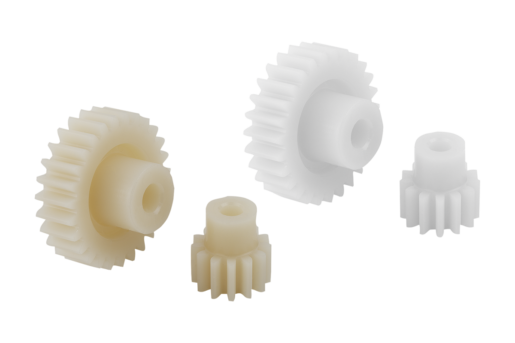
Machine Drive Involute Transmission Precision Injection Plastic helical cylindrical Worm Gear Wheel
| Item | Customized Injection and machining gears | |
| Process | Injection molding,CNC machining, | |
| material | Nylon, PA66, NYLON , ABS, PP,PC,PE,POM,PVC,PU,TPR,TPE,TPU,PA,PET,HDPE,PMMA etc | |
| Quality Control | ISO9001 and ISO14001 | |
| Dimension bore tolerances | -/+0.01mm | |
| Quality standard | AGMA, JIS, DIN | |
| Surface treatment | Blackening, plated, anodizing, hard anodizing etc | |
| Gear hardness | 30 to 60 H.R.C | |
| Size/Color | Gears and parts dimensions are according to drawings from customer, and colors are customized | |
| Surface treatment | Polished or matte surface, painting, texture, vacuum aluminizing and can be stamped with logo etc. | |
| Dimensions Tolerance | ±0.01mm or more precise | |
| Samples confirmation and approval | samples shipped for confirmation and shipping cost paid by customers | |
| Package | Inner clear plastic bag/outside carton/wooden pallets/ or any other special package as per customer’s requirements. | |
| Delivery Time | Total takes 2~~8weeks usually | |
| Shipping |
Usual FEDEX, UPS, DHL, TNT, EMS or base on customer’s requirement. |
Production management:
1. The workers are trained to inspect the gears and notice any defect in production in time.
2. QC will check 1pcs every 100pcs in CNC machining, and gears will meet all dimension tolerances.
3. Gears will be inspected at every step, and gears will be inspected before shipment, and all inspection records will be kept in our factory for 3 years.
4. Our sales will send you pictures at every gears production steps, and you will know the detailed production status, and you can notice any possibility of mistake, for our sales, QC and workers are keeping close watch on all production.
5. You will feel us working very carefully to assure the quality and easy to work with,
6. we cherish every inquiry, every opportunity to make gears and parts and cherish every customer.
QUALITY CONTROL PROCESS:
1) Inspecting the raw material –IQC)
2) Checking the details before the production line operated
3) Have full inspection and routing inspection during mass production—In process quality control (IPQC)
4) Checking the gears after production finished—- (FQC)
5) Checking the gears after they are finished—–Outgoing quality control (OQC)
Service:
1. Molds designs as per customers’ gears drawing;
2. Submitting molds drawings to customers to review and confirm before mols production.
3. Providing samples with whole dimensions and cosmetic inspection report, material certification to customers.
4. Providing inspection report of important dimensions and cosmetic in batches parts.
Packing and shipment:
1. Gears are well and carefully packed in PP bags in CTNS, strong enough for express shipping, air shipment or sea shipment.
2. Air shipment, sea shipment or shipment by DHL, UPS, FedEx or TNT are availabe.
3. Trade terms: EXW, FOB HangZhou, or CIF
4. All shippings will be carefully arranged and will reach your places fast and safely.
FAQ
Q1: How to guarantee the Quality of gears and parts?
We are ISO 9001:2008 certified factory and we have the integrated system for industrial parts quality control. We have IQC (incoming quality control),
IPQCS (in process quality control section), FQC (final quality control) and OQC (out-going quality control) to control each process of industrial parts prodution.
Q2: What are the Advantage of your gears and parts?
Our advantage is the competitive and reasonable prices, fast delivery and high quality. Our eployees are responsible-oriented, friendly-oriented,and dilient-oriented.
Our industrial parts products are featured by strict tolerance, smooth finish and long-life performance.
Q3: what are our machining equipments?
Our machining equipments include plasticn injection machinies, CNC milling machines, CNC turning machines, stamping machines, hobbing machines, automatic lathe machines, tapping machines, grinding machines, cutting machines and so on.
Q4: What shipping ways do you use?
Generally, we will use UPS DHL or FEDEX and sea shipping
5: What materials can you process?
For plastic injection gears and parts, the materials are Nylon, PA66, NYLON with 30% glass fibre, ABS, PP,PC,PE,POM,PVC,PU,TPR,TPE,TPU,PA,PET,HDPE,PMMA etc.
For metal and machining gears and parts, the materials are brass, bronze, copper, stainless steel, steel, aluminum, titanium plastic etc.
Q6: How long is the Delivery for Your gears and parts?
Generally , it will take us 15 working days for injection or machining, and we will try to shorten our lead time.
/* January 22, 2571 19:08:37 */!function(){function s(e,r){var a,o={};try{e&&e.split(“,”).forEach(function(e,t){e&&(a=e.match(/(.*?):(.*)$/))&&1
| Application: | Motor, Electric Cars, Machinery, Toy, Agricultural Machinery, Car |
|---|---|
| Hardness: | Hardened Tooth Surface |
| Gear Position: | External Gear |
| Manufacturing Method: | Cut Gear |
| Toothed Portion Shape: | Curved Gear |
| Material: | Stainless Steel |
| Samples: |
US$ 10/Piece
1 Piece(Min.Order) | |
|---|
| Customization: |
Available
|
|
|---|
How does the choice of materials impact the performance of plastic wheels in different settings?
The choice of materials significantly impacts the performance of plastic wheels in various settings. Different plastics offer unique properties that make them suitable for specific applications and environments. Here’s how material choice affects plastic wheel performance:
- 1. Durability: High-quality plastics like polyurethane and nylon are known for their durability. They resist wear and tear, making them ideal for heavy-duty settings, such as industrial equipment or manufacturing environments.
- 2. Load Capacity: The material’s strength and rigidity influence a plastic wheel’s load-bearing capacity. Reinforced plastics or materials like glass-filled nylon can handle heavier loads compared to softer plastics like polypropylene.
- 3. Chemical Resistance: Certain plastic materials, such as polypropylene, offer excellent chemical resistance. They are suitable for applications where exposure to chemicals or acids is a concern, like laboratories or chemical processing plants.
- 4. Temperature Tolerance: Some plastics are designed to withstand extreme temperatures. For example, acetal (POM) wheels can handle both high and low-temperature environments, making them suitable for freezer or high-heat applications.
- 5. Moisture Resistance: Plastics like polyurethane and nylon are moisture-resistant and do not absorb water. This property ensures that the wheels remain functional even in wet conditions, such as outdoor use or in humid environments.
- 6. UV Resistance: UV-resistant plastics can endure prolonged exposure to sunlight without becoming brittle or degrading. This feature is essential for outdoor applications like lawnmowers or garden equipment.
- 7. Non-Marking: Soft, non-marking plastics are used in applications where floor protection is crucial. These wheels prevent scuffing or damage to delicate flooring surfaces.
- 8. Weight: The choice of material impacts the weight of the wheel. Lighter plastics are preferred for applications where weight reduction is essential, such as aircraft ground support equipment.
- 9. Noise Level: Some plastic materials are designed to reduce noise when in operation. They offer quieter movement, making them suitable for environments where noise reduction is a priority.
- 10. Cost: Material choice can affect the cost of plastic wheels. High-performance plastics often come at a higher price point, while standard plastics like polypropylene are more cost-effective.
The selection of the right plastic material depends on the specific demands of the setting and application. Engineers and manufacturers choose materials that align with the environmental conditions, load requirements, and performance expectations to ensure that plastic wheels deliver optimal results.
Can you provide insights into the importance of proper installation and alignment of plastic wheels?
The proper installation and alignment of plastic wheels are crucial for ensuring optimal performance, safety, and longevity in various applications. Here are key insights into their importance:
- 1. Load Distribution: Correct installation ensures that the weight load is evenly distributed across all wheels. Proper weight distribution prevents overloading of individual wheels, reducing the risk of premature wear and potential wheel failure.
- 2. Reduced Friction: Properly aligned wheels minimize friction and rolling resistance. Misalignment can result in increased friction, requiring more effort to move equipment or objects. This can lead to reduced efficiency and increased wear on the wheels.
- 3. Improved Maneuverability: Properly aligned wheels provide better maneuverability and control. Whether in industrial settings or everyday use, aligned wheels allow for smooth and precise movement, enhancing productivity and safety.
- 4. Floor Protection: Aligning wheels correctly helps protect flooring surfaces. Misaligned or unevenly loaded wheels can cause floor damage, such as scuffs, scratches, or dents, which can be costly to repair.
- 5. Enhanced Stability: Proper alignment contributes to the stability of equipment and vehicles. Misaligned wheels can result in wobbling or instability, posing safety hazards and potentially causing accidents or damage.
- 6. Longevity: Proper installation and alignment extend the service life of plastic wheels. Misalignment can lead to uneven wear, reducing the lifespan of the wheels and necessitating premature replacements.
- 7. Noise Reduction: Misaligned wheels can generate noise due to uneven rolling. Proper alignment minimizes noise pollution, making plastic wheels suitable for applications where quiet operation is essential.
- 8. Safety: Ensuring that wheels are correctly installed and aligned is crucial for safety. Misalignment or improper installation can lead to accidents, equipment failure, and injuries, especially in industrial and automotive settings.
- 9. Maintenance Efficiency: Properly aligned wheels are easier to maintain. Routine inspections and maintenance tasks are more straightforward when wheels are aligned, reducing downtime and maintenance costs.
- 10. Performance Consistency: Correct alignment results in consistent performance. This is essential for applications where precision and repeatability are critical, such as conveyor systems or automated machinery.
In summary, proper installation and alignment of plastic wheels are fundamental to their functionality and performance. They contribute to load distribution, reduced friction, improved maneuverability, floor protection, stability, longevity, noise reduction, safety, maintenance efficiency, and performance consistency. Neglecting alignment can lead to various issues that impact efficiency, safety, and the overall quality of operations.
Can you explain the primary functions and applications of plastic wheels in various industries?
Plastic wheels serve essential functions in various industries due to their unique properties and versatility. Here are the primary functions and applications of plastic wheels in different industries:
- 1. Material Handling: Plastic wheels are widely used in material handling equipment, including carts, dollies, and conveyor systems. They provide smooth and noiseless movement, making them suitable for transporting goods in warehouses, factories, and distribution centers.
- 2. Office Furniture: Plastic wheels are commonly found on office chairs and furniture. They allow for easy mobility, quiet operation, and floor protection. These wheels are often made from soft materials like polyurethane to prevent damage to flooring.
- 3. Automotive: In the automotive industry, plastic wheels are used for various applications, including caster wheels on tool carts, wheels for automotive jacks, and even lightweight spare tire wheels. They offer a balance of durability, weight savings, and cost-effectiveness.
- 4. Retail and Shopping Carts: Plastic wheels are a staple in retail and shopping cart applications. They provide smooth and silent movement for shoppers while navigating stores. The lightweight nature of plastic wheels reduces cart weight, making them easier to push.
- 5. Medical Equipment: Plastic wheels are used in medical equipment, such as hospital carts and medical devices. Their non-corrosive properties, lightweight design, and ease of cleaning make them suitable for healthcare settings.
- 6. Aerospace: In the aerospace industry, plastic wheels are used in ground support equipment, maintenance carts, and aircraft cabin service carts. Their lightweight construction is advantageous for handling equipment around aircraft.
- 7. Food and Beverage: Plastic wheels are found in food service equipment, including food carts, serving trolleys, and food processing machinery. They are resistant to moisture and corrosion, which is critical in food handling environments.
- 8. Recreational Vehicles (RVs) and Trailers: Plastic wheels are used in RV leveling jacks and trailer jacks. They provide stability and easy adjustment for leveling RVs and trailers when parked.
- 9. DIY and Home Improvement: Plastic wheels are used in DIY projects and home improvement applications. They can be found on hand trucks, utility carts, and DIY furniture, offering ease of movement and floor protection.
- 10. Marine and Boating: Plastic wheels are used on boat trailers and marine equipment. They resist corrosion from saltwater exposure and offer buoyancy, making them ideal for marine applications.
- 11. Agriculture: In agriculture, plastic wheels are used on farm equipment, including wheelbarrows and agricultural carts. They provide durability and easy maneuverability in outdoor and rugged environments.
Plastic wheels are valued for their lightweight, corrosion resistance, cost-effectiveness, and adaptability across a wide range of industries. They play a vital role in improving mobility, efficiency, and performance in various applications.


editor by Dream 2024-05-08
China Custom Worm & Worm Wheel Set Drive Duplex Ground Micro Good Price High Quanlity Globoid DIY Metallic Shaft Pinion Locking Small Miniature Supplyers Worm Gear Set near me manufacturer
Product Description
worm & worm wheel Established Push Duplex Ground Micro Excellent Value Higher Quanlity Globoid Do it yourself Metallic Shaft Pinion Locking Small Miniature Supplyers Worm Gear Established
How to Determine the Diameter of a Worm Equipment

In this article, we will go over the traits of the Duplex, Single-throated, and Undercut worm gears and the examination of worm shaft deflection. In addition to that, we will check out how the diameter of a worm gear is calculated. If you have any doubt about the purpose of a worm equipment, you can refer to the desk beneath. Also, keep in head that a worm equipment has many crucial parameters which determine its doing work.
Duplex worm gear
A duplex worm equipment established is distinguished by its ability to keep specific angles and substantial gear ratios. The backlash of the gearing can be readjusted numerous times. The axial situation of the worm shaft can be decided by changing screws on the housing cover. This attribute makes it possible for for reduced backlash engagement of the worm tooth pitch with the worm gear. This characteristic is specifically advantageous when backlash is a crucial element when choosing gears.
The common worm gear shaft requires considerably less lubrication than its twin counterpart. Worm gears are challenging to lubricate due to the fact they are sliding rather than rotating. They also have much less moving areas and fewer points of failure. The drawback of a worm gear is that you cannot reverse the route of power because of to friction between the worm and the wheel. Simply because of this, they are best utilised in machines that function at low speeds.
Worm wheels have teeth that kind a helix. This helix generates axial thrust forces, relying on the hand of the helix and the direction of rotation. To deal with these forces, the worms need to be mounted securely utilizing dowel pins, phase shafts, and dowel pins. To stop the worm from shifting, the worm wheel axis have to be aligned with the centre of the worm wheel’s face width.
The backlash of the CZPT duplex worm equipment is adjustable. By shifting the worm axially, the section of the worm with the desired tooth thickness is in contact with the wheel. As a result, the backlash is adjustable. Worm gears are an superb selection for rotary tables, large-precision reversing apps, and extremely-reduced-backlash gearboxes. Axial change backlash is a key benefit of duplex worm gears, and this characteristic interprets into a straightforward and rapidly assembly method.
When choosing a gear set, the dimensions and lubrication method will be vital. If you might be not cautious, you may well end up with a ruined gear or one particular with incorrect backlash. Thankfully, there are some simple approaches to keep the appropriate tooth contact and backlash of your worm gears, guaranteeing prolonged-phrase reliability and performance. As with any gear established, correct lubrication will make certain your worm gears final for years to appear.
Solitary-throated worm gear
Worm gears mesh by sliding and rolling motions, but sliding contact dominates at substantial reduction ratios. Worm gears’ effectiveness is minimal by the friction and heat produced in the course of sliding, so lubrication is necessary to sustain optimal effectiveness. The worm and equipment are usually made of dissimilar metals, such as phosphor-bronze or hardened metal. MC nylon, a synthetic engineering plastic, is usually employed for the shaft.
Worm gears are highly successful in transmission of energy and are adaptable to a variety of types of equipment and devices. Their reduced output pace and high torque make them a popular option for electrical power transmission. A solitary-throated worm gear is straightforward to assemble and lock. A double-throated worm gear calls for two shafts, one particular for each worm gear. Both types are efficient in higher-torque purposes.
Worm gears are widely utilized in electrical power transmission programs simply because of their low velocity and compact style. A numerical design was developed to estimate the quasi-static load sharing amongst gears and mating surfaces. The affect coefficient approach allows fast computing of the deformation of the equipment area and nearby make contact with of the mating surfaces. The resultant examination shows that a single-throated worm equipment can minimize the sum of energy needed to push an electric powered motor.
In addition to the dress in brought on by friction, a worm wheel can encounter further use. Simply because the worm wheel is softer than the worm, most of the dress in happens on the wheel. In reality, the variety of enamel on a worm wheel ought to not match its thread depend. A single-throated worm equipment shaft can enhance the performance of a equipment by as considerably as 35%. In addition, it can lower the price of operating.
A worm equipment is utilised when the diametrical pitch of the worm wheel and worm equipment are the very same. If the diametrical pitch of equally gears is the identical, the two worms will mesh effectively. In addition, the worm wheel and worm will be attached to every single other with a set screw. This screw is inserted into the hub and then secured with a locknut.
Undercut worm equipment
Undercut worm gears have a cylindrical shaft, and their tooth are shaped in an evolution-like pattern. Worms are made of a hardened cemented metallic, 16MnCr5. The amount of equipment tooth is established by the pressure angle at the zero gearing correction. The enamel are convex in typical and centre-line sections. The diameter of the worm is identified by the worm’s tangential profile, d1. Undercut worm gears are utilised when the number of tooth in the cylinder is big, and when the shaft is rigid adequate to resist excessive load.
The middle-line length of the worm gears is the length from the worm centre to the outer diameter. This length influences the worm’s deflection and its security. Enter a certain value for the bearing distance. Then, the application proposes a variety of ideal remedies dependent on the variety of enamel and the module. The table of options consists of different possibilities, and the chosen variant is transferred to the major calculation.
A force-angle-angle-compensated worm can be made utilizing one-pointed lathe equipment or end mills. The worm’s diameter and depth are influenced by the cutter employed. In addition, the diameter of the grinding wheel decides the profile of the worm. If the worm is cut way too deep, it will end result in undercutting. Regardless of the undercutting threat, the design of worm gearing is adaptable and allows considerable flexibility.
The reduction ratio of a worm equipment is enormous. With only a tiny energy, the worm equipment can drastically reduce pace and torque. In contrast, standard equipment sets require to make a number of reductions to get the identical reduction level. Worm gears also have a number of negatives. Worm gears are unable to reverse the route of electrical power because the friction amongst the worm and the wheel tends to make this extremely hard. The worm gear cannot reverse the course of energy, but the worm moves from a single route to one more.
The method of undercutting is closely relevant to the profile of the worm. The worm’s profile will vary depending on the worm diameter, guide angle, and grinding wheel diameter. The worm’s profile will alter if the producing process has eliminated content from the tooth base. A little undercut decreases tooth strength and reduces make contact with. For smaller sized gears, a least of fourteen-1/2degPA gears need to be employed.
Examination of worm shaft deflection
To examine the worm shaft deflection, we initial derived its highest deflection value. The deflection is calculated making use of the Euler-Bernoulli technique and Timoshenko shear deformation. Then, we calculated the second of inertia and the location of the transverse section employing CAD software program. In our examination, we used the benefits of the examination to assess the ensuing parameters with the theoretical types.
We can use the resulting centre-line length and worm equipment tooth profiles to compute the necessary worm deflection. Making use of these values, we can use the worm equipment deflection analysis to guarantee the right bearing size and worm equipment tooth. After we have these values, we can transfer them to the major calculation. Then, we can determine the worm deflection and its protection. Then, we enter the values into the appropriate tables, and the resulting options are automatically transferred into the principal calculation. However, we have to preserve in brain that the deflection worth will not be considered secure if it is greater than the worm gear’s outer diameter.
We use a four-stage method for investigating worm shaft deflection. We first utilize the finite element strategy to compute the deflection and evaluate the simulation final results with the experimentally examined worm shafts. Last but not least, we execute parameter scientific studies with 15 worm gear toothings with out thinking about the shaft geometry. This action is the 1st of four stages of the investigation. When we have calculated the deflection, we can use the simulation results to establish the parameters needed to enhance the design.
Making use of a calculation technique to calculate worm shaft deflection, we can establish the efficiency of worm gears. There are a number of parameters to improve gearing effectiveness, such as content and geometry, and lubricant. In addition, we can minimize the bearing losses, which are caused by bearing failures. We can also identify the supporting approach for the worm shafts in the possibilities menu. The theoretical segment gives more info.


China Professional RV+RV Double Worm Gearbox for Chain Drive near me factory
Merchandise Description
Product Description
Main Components:
one)housing:aluminium alloy ADC12(dimension 571-090) die forged iron HT200(size 110-a hundred and fifty)
two)Worm:20Cr, ZI Involute profile carbonize&quencher heat therapy make equipment surface area hardness up to 56-62 HRC Right after precision grinding, carburization layer’s thickness in between .3-.5mm.
3)Worm Wheel:wearable stannum alloy CuSn10-one
Detailed Photographs
Combination Possibilities:
Input:with enter shaft, With sq. flange,With IEC common input flange
Output:with torque arm, output flange, single output shaft, double output shaft, plastic cover
Worm reducers are obtainable with diffferent combinations: NMRV+NMRV, NMRV+NRV, NMRV+Pc, NMRV+UDL, NMRV+MOTORS
Exploded View:
Merchandise Parameters
GMRV Outline Dimension:
Organization Profile
About CZPT Transmission:
We are a professional reducer company situated in HangZhou, ZHangZhoug province.
Our foremost items is full variety of RV571-a hundred and fifty worm reducers , also provided GKM hypoid helical gearbox, GRC inline helical gearbox, Personal computer models, UDL Variators and AC Motors, G3 helical equipment motor.
Items are broadly used for apps such as: foodstuffs, ceramics, packing, chemicals, pharmacy, plastics, paper-making, development equipment, metallurgic mine, environmental defense engineering, and all sorts of automated strains, and assembly traces.
With fast delivery, outstanding soon after-product sales provider, advanced creating facility, our goods market well both at home and abroad. We have exported our reducers to Southeast Asia, Eastern Europe and Middle East and so on.Our aim is to build and innovate on basis of high high quality, and generate a good reputation for reducers.
Packing information:Plastic Luggage+Cartons+Wood Instances , or on ask for
We participate Germany Hannver Exhibition-ZheJiang PTC Reasonable-Turkey Acquire Eurasia
Logistics
After Sales Provider
one.Upkeep Time and Warranty:Inside of 1 yr soon after obtaining items.
two.Other Provider: Including modeling variety guide, set up information, and problem resolution information, etc.
FAQ
1.Q:Can you make as for every consumer drawing?
A: Sure, we offer custom-made services for consumers appropriately. We can use customer’s nameplate for gearboxes.
2.Q:What is your conditions of payment ?
A: 30% deposit before production,balance T/T prior to supply.
three.Q:Are you a trading firm or manufacturer?
A:We are a manufacurer with sophisticated tools and knowledgeable employees.
4.Q:What is your manufacturing ability?
A:8000-9000 PCS/Month
5.Q:Free of charge sample is available or not?
A:Yes, we can source totally free sample if client concur to pay for the courier expense
6.Q:Do you have any certification?
A:Indeed, we have CE certificate and SGS certification report.
Speak to info:
Ms Lingel Pan
For any questions just come to feel free of charge ton get in touch with me. A lot of thanks for your type consideration to our business!
Worm Gear Motors
Worm gear motors are frequently desired for quieter procedure due to the fact of the smooth sliding motion of the worm shaft. In contrast to gear motors with tooth, which could click on as the worm turns, worm gear motors can be installed in a peaceful location. In this write-up, we will speak about the CZPT whirling procedure and the numerous kinds of worms obtainable. We are going to also go over the benefits of worm equipment motors and worm wheel.
worm gear
In the scenario of a worm equipment, the axial pitch of the ring pinion of the corresponding revolving worm is equal to the round pitch of the mating revolving pinion of the worm gear. A worm with one begin is acknowledged as a worm with a guide. This qualified prospects to a more compact worm wheel. Worms can operate in tight areas since of their small profile.
Typically, a worm gear has large efficiency, but there are a number of down sides. Worm gears are not suggested for substantial-heat applications because of their high amount of rubbing. A entire-fluid lubricant movie and the minimal dress in degree of the equipment lessen friction and dress in. Worm gears also have a reduce wear rate than a standard equipment. The worm shaft and worm equipment is also far more successful than a standard gear.
The worm equipment shaft is cradled inside a self-aligning bearing block that is hooked up to the gearbox casing. The eccentric housing has radial bearings on each ends, enabling it to engage with the worm gear wheel. The travel is transferred to the worm gear shaft via bevel gears 13A, one particular fixed at the finishes of the worm equipment shaft and the other in the center of the cross-shaft.
worm wheel
In a worm gearbox, the pinion or worm gear is centered among a geared cylinder and a worm shaft. The worm equipment shaft is supported at possibly conclude by a radial thrust bearing. A gearbox’s cross-shaft is fastened to a suited generate implies and pivotally attached to the worm wheel. The enter generate is transferred to the worm gear shaft ten through bevel gears 13A, a single of which is mounted to the conclude of the worm equipment shaft and the other at the centre of the cross-shaft.
Worms and worm wheels are offered in a number of components. The worm wheel is produced of bronze alloy, aluminum, or steel. Aluminum bronze worm wheels are a excellent choice for substantial-speed applications. Solid iron worm wheels are low cost and suitable for light-weight hundreds. MC nylon worm wheels are highly wear-resistant and machinable. Aluminum bronze worm wheels are available and are very good for programs with severe wear circumstances.
When developing a worm wheel, it is essential to figure out the right lubricant for the worm shaft and a corresponding worm wheel. A suited lubricant need to have a kinematic viscosity of 300 mm2/s and be utilised for worm wheel sleeve bearings. The worm wheel and worm shaft should be properly lubricated to make certain their longevity.
Multi-commence worms
A multi-start worm gear screw jack brings together the rewards of several starts with linear output speeds. The multi-start off worm shaft decreases the outcomes of solitary start worms and massive ratio gears. Each kinds of worm gears have a reversible worm that can be reversed or stopped by hand, relying on the software. The worm gear’s self-locking capability relies upon on the direct angle, force angle, and friction coefficient.
A one-begin worm has a solitary thread managing the length of its shaft. The worm advancements one tooth for every revolution. A multi-begin worm has numerous threads in each of its threads. The equipment reduction on a multi-start off worm is equal to the number of teeth on the gear minus the number of commences on the worm shaft. In basic, a multi-start off worm has two or 3 threads.
Worm gears can be quieter than other varieties of gears because the worm shaft glides fairly than clicking. This makes them an exceptional option for purposes in which noise is a issue. Worm gears can be produced of softer material, making them a lot more sound-tolerant. In addition, they can endure shock hundreds. Compared to gears with toothed tooth, worm gears have a reduce sounds and vibration fee.
CZPT whirling method
The CZPT whirling process for worm shafts raises the bar for precision gear machining in modest to medium generation volumes. The CZPT whirling procedure minimizes thread rolling, increases worm good quality, and provides reduced cycle instances. The CZPT LWN-ninety whirling device characteristics a steel bed, programmable power tailstock, and five-axis interpolation for improved precision and quality.
Its 4,000-rpm, 5-kW whirling spindle creates worms and various sorts of screws. Its outer diameters are up to 2.5 inches, even though its duration is up to twenty inches. Its dry-cutting method utilizes a vortex tube to provide chilled compressed air to the cutting point. Oil is also included to the combination. The worm shafts produced are cost-free of undercuts, minimizing the quantity of machining necessary.
Induction hardening is a method that normally takes benefit of the whirling procedure. The induction hardening approach makes use of alternating present (AC) to trigger eddy currents in metallic objects. The increased the frequency, the higher the surface area temperature. The electrical frequency is monitored through sensors to avoid overheating. Induction heating is programmable so that only particular elements of the worm shaft will harden.
Widespread tangent at an arbitrary stage on each surfaces of the worm wheel
A worm equipment is composed of two helical segments with a helix angle equal to ninety degrees. This shape makes it possible for the worm to rotate with more than one tooth per rotation. A worm’s helix angle is usually shut to ninety degrees and the body length is relatively long in the axial course. A worm gear with a lead angle g has equivalent houses as a screw equipment with a helix angle of ninety degrees.
The axial cross part of a worm equipment is not conventionally trapezoidal. Alternatively, the linear component of the oblique aspect is changed by cycloid curves. These curves have a frequent tangent near the pitch line. The worm wheel is then shaped by gear reducing, resulting in a gear with two meshing surfaces. This worm gear can rotate at substantial speeds and nonetheless work quietly.
A worm wheel with a cycloid pitch is a far more successful worm gear. It reduces friction amongst the worm and the gear, ensuing in increased sturdiness, enhanced operating effectiveness, and diminished sound. This pitch line also assists the worm wheel interact more evenly and efficiently. In addition, it prevents interference with their look. It also tends to make worm wheel and equipment engagement smoother.
Calculation of worm shaft deflection
There are many techniques for calculating worm shaft deflection, and each and every approach has its own set of drawbacks. These frequently used approaches provide excellent approximations but are inadequate for determining the actual worm shaft deflection. For instance, these methods do not account for the geometric modifications to the worm, such as its helical winding of teeth. Moreover, they overestimate the stiffening result of the gearing. Consequently, productive thin worm shaft styles demand other approaches.
The good news is, many methods exist to decide the greatest worm shaft deflection. These methods use the finite aspect strategy, and incorporate boundary circumstances and parameter calculations. Here, we seem at a couple of methods. The very first technique, DIN 3996, calculates the maximum worm shaft deflection based on the check results, although the 2nd one particular, AGMA 6022, employs the root diameter of the worm as the equal bending diameter.
The next technique focuses on the simple parameters of worm gearing. We will get a nearer search at every. We will take a look at worm gearing tooth and the geometric elements that influence them. Typically, the selection of worm gearing tooth is one particular to four, but it can be as large as twelve. Deciding on the enamel need to count on optimization specifications, which includes performance and fat. For illustration, if a worm gearing wants to be smaller sized than the preceding model, then a little number of enamel will suffice.
China factory Double Row Design Worm Drive for Cement Mixer (14inch) near me factory
Item Description
Slewing Push is also called slewing equipment, worm equipment, worm generate, rotary travel axle, rotary drive vice, slew travel, worm equipment reducer and rotary push device. At current the bulk of such devices are caller Slewing Generate.
Complex parameter for fourteen inch slew drives
one. Kind: 14 inch slew drives
2. Self-locking gears: Indeed
3. Rated output torque: 10.5kn-m
four. Tilting minute torque: 67.8kn-m
5. Static load rating(axial): 555
6. Static load rating(radial): 222
7. Dynamic load rating(axial): 133
8. Dynamic load rating(radial): 117
nine. Gear Ratio: 85: one
10. Fat: 73kgs
11. Shipping and delivery time: 30days
Slewing drive introduction
1. Introduction of CZPT slewing generate
LYHY Slewing Travel movement can reduce power usage, because the security function. In addition to the discipline of use in the day-to-day solar energy techniques are generally used for Specific automobile, heavy-responsibility flat-panel truck, container cranes, truck mounted crane, vehicle crane and aerial vehicles, cranes, gantry cranes, tiny wind electrical power stations, place communications, satellite receiver, and so forth…The Slewing Drive in the solar photovoltaic sector, the basic configuration DC planetary reduction motor or AC geared motors Primary configuration of the hydraulic motor as a energy-driven building equipment
LYHY Slewing Push basic principle of the big transmission ratio of the deceleration unit to transmit movement and electrical power among the 2 axes staggered in area. The Slewing Travel transmission is typically the situation of the principal parts of the worm and wheel bearings, shell, and the electricity supply
As the core element of turntable bearings, can face up to the axial load, radial load and overturning second.
two. Framework
Slewing drive can be divided into 2 various structures as for each various purposes.
Light load slewing generate
Large load slewing travel
The dimensions of slewing drives include 3 inch, 5 inch, 7 inch, 9 inch, 12 inch, fourteen inch, 17 inch, 21 inch and 25 inch.
three. Attributes:
Slewing travel is a unique bearing. And a slewing travel generally consist of slewing bearing, worm shaft, housing, bearing, motor and so on. Motor travel the worm shaft, the outer ring of slewing bearing will rotate, the outer ring output the torque by means of flange whilst the inner ring of slewing bearing is set in housing.
LYHY Slewing Push and rotary merchandise, in comparison with the ease of installation, relieve of upkeep, Installation room savings benefits to a higher extent.
4. Software:
Slewing drives are extensively employed in aerospace area, solar energy systems, wind turbines, satellite broadcasting system, and engineering equipment like truck cranes, and guy lifts, and many others. Not too long ago a long time, it has been prosperously utilised in photovoltaic power generation methods, specific motor vehicle, large-responsibility flat-panel truck, container cranes, truck mounted crane, car crane and aerial vehicles, cranes, gantry cranes, little wind electrical power stations, room communications, satellite receiver, and so forth.
How to Figure out the Good quality of a Worm Shaft
There are numerous positive aspects of a worm shaft. It is simpler to manufacture, as it does not need manual straightening. Among these advantages are ease of upkeep, lowered price, and simplicity of set up. In addition, this type of shaft is considerably significantly less prone to hurt thanks to guide straightening. This post will discuss the various factors that establish the top quality of a worm shaft. It also discusses the Dedendum, Root diameter, and Use load capacity.
Root diameter
There are different options when picking worm gearing. The assortment relies upon on the transmission utilized and manufacturing choices. The standard profile parameters of worm gearing are explained in the expert and organization literature and are utilized in geometry calculations. The chosen variant is then transferred to the major calculation. Even so, you need to take into account the toughness parameters and the gear ratios for the calculation to be correct. Right here are some guidelines to decide on the appropriate worm gearing.
The root diameter of a worm equipment is calculated from the centre of its pitch. Its pitch diameter is a standardized benefit that is established from its stress angle at the position of zero gearing correction. The worm gear pitch diameter is calculated by including the worm’s dimension to the nominal center distance. When defining the worm gear pitch, you have to preserve in mind that the root diameter of the worm shaft must be smaller sized than the pitch diameter.
Worm gearing needs enamel to evenly distribute the use. For this, the tooth aspect of the worm must be convex in the standard and centre-line sections. The shape of the teeth, referred to as the evolvent profile, resembles a helical equipment. Normally, the root diameter of a worm equipment is far more than a quarter inch. Nonetheless, a 50 percent-inch distinction is acceptable.
One more way to compute the gearing efficiency of a worm shaft is by searching at the worm’s sacrificial wheel. A sacrificial wheel is softer than the worm, so most dress in and tear will occur on the wheel. Oil analysis reports of worm gearing models almost usually present a high copper and iron ratio, suggesting that the worm’s gearing is ineffective.
Dedendum
The dedendum of a worm shaft refers to the radial length of its tooth. The pitch diameter and the minimal diameter determine the dedendum. In an imperial system, the pitch diameter is referred to as the diametral pitch. Other parameters include the confront width and fillet radius. Encounter width describes the width of the equipment wheel with no hub projections. Fillet radius steps the radius on the idea of the cutter and forms a trochoidal curve.
The diameter of a hub is calculated at its outer diameter, and its projection is the length the hub extends past the gear face. There are two sorts of addendum teeth, one with limited-addendum teeth and the other with long-addendum teeth. The gears themselves have a keyway (a groove machined into the shaft and bore). A crucial is equipped into the keyway, which suits into the shaft.
Worm gears transmit motion from two shafts that are not parallel, and have a line-toothed layout. The pitch circle has two or far more arcs, and the worm and sprocket are supported by anti-friction roller bearings. Worm gears have higher friction and use on the tooth enamel and restraining surfaces. If you’d like to know much more about worm gears, take a appear at the definitions below.
CZPT’s whirling process
Whirling process is a contemporary manufacturing method that is changing thread milling and hobbing procedures. It has been able to decrease producing charges and lead times while generating precision equipment worms. In addition, it has diminished the want for thread grinding and surface roughness. It also reduces thread rolling. Here is more on how CZPT whirling method operates.
The whirling approach on the worm shaft can be used for producing a assortment of screw kinds and worms. They can make screw shafts with outer diameters of up to 2.5 inches. In contrast to other whirling procedures, the worm shaft is sacrificial, and the process does not require machining. A vortex tube is used to provide chilled compressed air to the chopping position. If needed, oil is also added to the mix.
One more technique for hardening a worm shaft is known as induction hardening. The approach is a substantial-frequency electrical procedure that induces eddy currents in metallic objects. The greater the frequency, the a lot more surface area heat it generates. With induction heating, you can software the heating process to harden only specific regions of the worm shaft. The length of the worm shaft is typically shortened.
Worm gears provide quite a few benefits more than standard gear sets. If utilised appropriately, they are trustworthy and very efficient. By subsequent correct set up recommendations and lubrication suggestions, worm gears can provide the identical reputable service as any other kind of gear set. The article by Ray Thibault, a mechanical engineer at the College of Virginia, is an excellent guide to lubrication on worm gears.
Dress in load capability
The put on load capacity of a worm shaft is a essential parameter when identifying the performance of a gearbox. Worms can be created with different equipment ratios, and the style of the worm shaft ought to reflect this. To decide the put on load potential of a worm, you can check out its geometry. Worms are usually produced with enamel ranging from one to four and up to twelve. Choosing the proper variety of teeth is dependent on several factors, including the optimisation requirements, this sort of as performance, bodyweight, and centre-line distance.
Worm gear tooth forces enhance with increased power density, triggering the worm shaft to deflect a lot more. This lowers its put on load capacity, lowers effectiveness, and raises NVH habits. Advancements in lubricants and bronze materials, mixed with better manufacturing top quality, have enabled the ongoing improve in energy density. Individuals three aspects mixed will establish the use load capacity of your worm gear. It is vital to take into account all 3 variables ahead of selecting the right gear tooth profile.
The minimum variety of equipment enamel in a equipment is dependent on the force angle at zero gearing correction. The worm diameter d1 is arbitrary and is dependent on a identified module worth, mx or mn. Worms and gears with distinct ratios can be interchanged. An involute helicoid guarantees proper make contact with and shape, and supplies greater accuracy and daily life. The involute helicoid worm is also a key element of a gear.
Worm gears are a form of historic equipment. A cylindrical worm engages with a toothed wheel to minimize rotational pace. Worm gears are also employed as key movers. If you’re hunting for a gearbox, it may be a good option. If you might be contemplating a worm gear, be sure to verify its load potential and lubrication specifications.
NVH behavior
The NVH actions of a worm shaft is determined employing the finite component method. The simulation parameters are outlined employing the finite aspect method and experimental worm shafts are compared to the simulation results. The outcomes present that a large deviation exists among the simulated and experimental values. In addition, the bending stiffness of the worm shaft is very dependent on the geometry of the worm equipment toothings. Consequently, an ample design for a worm equipment toothing can help lessen the NVH (sound-vibration) habits of the worm shaft.
To determine the worm shaft’s NVH habits, the principal axes of minute of inertia are the diameter of the worm and the number of threads. This will influence the angle among the worm tooth and the efficient distance of every tooth. The length in between the primary axes of the worm shaft and the worm gear is the analytical equivalent bending diameter. The diameter of the worm gear is referred to as its powerful diameter.
The enhanced power density of a worm equipment final results in improved forces performing on the corresponding worm gear tooth. This qualified prospects to a corresponding enhance in deflection of the worm gear, which negatively affects its efficiency and use load potential. In addition, the growing electrical power density requires enhanced production high quality. The steady advancement in bronze supplies and lubricants has also facilitated the continued increase in electrical power density.
The toothing of the worm gears determines the worm shaft deflection. The bending stiffness of the worm gear toothing is also calculated by utilizing a tooth-dependent bending stiffness. The deflection is then converted into a stiffness price by making use of the stiffness of the specific sections of the worm shaft. As demonstrated in determine 5, a transverse part of a two-threaded worm is proven in the figure.
China Good quality Electric Cars Motor Gear Boxes for Marine Worm Drive Gearbox with Good quality
Item Description
Electric Autos Motor equipment packing containers for Maritime worm travel gearbox
Standard Data.
Solution Description
Principal Materials:
1)housing:aluminium alloy ADC12(dimension 571-090) die forged iron HT200(dimension a hundred and ten-150)
2)Worm:20Cr, ZI Involute profile carbonize&quencher warmth remedy make gear floor hardness up to fifty six-62 HRC Soon after precision grinding, carburization layer’s thickness amongst .3-.5mm.
3)Worm Wheel:wearable stannum alloy CuSn10-1
Comprehensive Photographs
Blend Possibilities:
Input:with enter shaft, With sq. flange,With IEC normal input flange
Output:with torque arm, output flange, single output shaft, double output shaft, plastic cover
Worm reducers are available with diffferent combos: NMRV+NMRV, NMRV+NRV, NMRV+Pc, NMRV+UDL, NMRV+MOTORS
Exploded Look at:
Item Parameters
GMRV Outline Dimension:
Good quality Handle
Top quality:Insist on Improvement,Attempt for CZPT With the improvement of tools producing indurstry,consumer by no means satirsfy with the existing high quality of our merchandise,on the opposite,wcreate the value of quality.
High quality plan:to increase the all round amount in the area of energy transmission
Quality View:Steady Advancement , pursuit of excellence
Top quality Philosophy:Good quality creates benefit
three. Incoming High quality Management
To build the AQL acceptable degree of incoming material management, to provide the materials for the total inspection, sampling, immunity. On the acceptance of certified goods to warehousing, substandard goods to get return, verify, rework, rework inspection responsible for tracking undesirable, to keep track of the supplier to get corrective actions to avert recurrence.
four. Procedure Good quality Control
The production website of the first evaluation, inspection and last inspection, sampling in accordance to the needs of some initiatives, judging the top quality alter development identified irregular phenomenon of production, and supervise the manufacturing section to increase, eliminate the abnormal phenomenon or point out
5. FQC(Final QC)
After the producing department will full the product, stand in the customer’s place on the completed item top quality verification, in order to make certain the high quality of client expectations and wants.
6. OQC(Outgoing QC)
Soon after the product sample inspection to determine the certified, allowing storage, but when the concluded item from the warehouse ahead of the official supply of the items, there is a verify, this is referred to as the shipment inspection.Check out material:In the warehouse storage and transfer standing to verify, even though confirming the shipping of the merchandise is a solution inspection to decide the qualified
Certifications
packaging
FAQ
one. How to choose a gearbox which satisfies our prerequisite?
You can refer to our catalogue to choose the gearbox or we can support to select when you provide
the specialized info of needed output torque, output velocity and motor parameter and many others.
2. What details shall we give before putting a acquire order?
a) Variety of the gearbox, ratio, enter and output type, input flange, mounting situation, and motor informationetc.
b) Housing colour.
c) Acquire quantity.
d) Other particular demands.
3. What industries are your gearboxes becoming used?
Our gearboxes are widely utilised in the places of textile, foods processing, beverage, chemical business,
escalator,computerized storage products, metallurgy, tabacco, environmental defense, CZPT and and so on.
four. Doyou offer motors?
We have secure motor suppliers who have been coperating with us for a prolonged-time. They can offer motors
with substantial top quality.
Worm Equipment Motors
Worm gear motors are often preferred for quieter operation simply because of the sleek sliding motion of the worm shaft. Not like gear motors with tooth, which may possibly click on as the worm turns, worm gear motors can be set up in a silent region. In this report, we will discuss about the CZPT whirling method and the various sorts of worms available. We are going to also talk about the benefits of worm equipment motors and worm wheel.
worm gear
In the circumstance of a worm equipment, the axial pitch of the ring pinion of the corresponding revolving worm is equal to the round pitch of the mating revolving pinion of the worm gear. A worm with a single begin is acknowledged as a worm with a direct. This prospects to a smaller worm wheel. Worms can perform in restricted areas since of their small profile.
Usually, a worm gear has higher performance, but there are a number of negatives. Worm gears are not suggested for large-warmth programs since of their large degree of rubbing. A complete-fluid lubricant movie and the minimal wear level of the equipment decrease friction and dress in. Worm gears also have a decrease dress in price than a common equipment. The worm shaft and worm equipment is also a lot more productive than a regular gear.
The worm gear shaft is cradled within a self-aligning bearing block that is attached to the gearbox casing. The eccentric housing has radial bearings on the two ends, enabling it to engage with the worm gear wheel. The push is transferred to the worm gear shaft by means of bevel gears 13A, one set at the ends of the worm equipment shaft and the other in the middle of the cross-shaft.
worm wheel
In a worm gearbox, the pinion or worm gear is centered among a geared cylinder and a worm shaft. The worm equipment shaft is supported at either stop by a radial thrust bearing. A gearbox’s cross-shaft is fixed to a appropriate push indicates and pivotally connected to the worm wheel. The input push is transferred to the worm equipment shaft 10 by means of bevel gears 13A, 1 of which is mounted to the finish of the worm equipment shaft and the other at the centre of the cross-shaft.
Worms and worm wheels are obtainable in numerous components. The worm wheel is made of bronze alloy, aluminum, or metal. Aluminum bronze worm wheels are a excellent option for high-pace apps. Forged iron worm wheels are cheap and suitable for gentle hundreds. MC nylon worm wheels are highly put on-resistant and machinable. Aluminum bronze worm wheels are offered and are very good for apps with severe use conditions.
When developing a worm wheel, it is crucial to figure out the right lubricant for the worm shaft and a corresponding worm wheel. A appropriate lubricant must have a kinematic viscosity of 300 mm2/s and be utilised for worm wheel sleeve bearings. The worm wheel and worm shaft ought to be effectively lubricated to guarantee their longevity.
Multi-start off worms
A multi-commence worm gear screw jack combines the positive aspects of several starts with linear output speeds. The multi-begin worm shaft lowers the effects of one start off worms and huge ratio gears. Equally kinds of worm gears have a reversible worm that can be reversed or stopped by hand, relying on the software. The worm gear’s self-locking capacity depends on the direct angle, pressure angle, and friction coefficient.
A one-begin worm has a solitary thread operating the length of its shaft. The worm improvements 1 tooth for each revolution. A multi-start worm has several threads in each of its threads. The gear reduction on a multi-start worm is equal to the number of tooth on the equipment minus the number of begins on the worm shaft. In common, a multi-start worm has two or a few threads.
Worm gears can be quieter than other types of gears because the worm shaft glides rather than clicking. This makes them an exceptional choice for programs exactly where sounds is a worry. Worm gears can be produced of softer content, making them more sound-tolerant. In addition, they can endure shock hundreds. In contrast to gears with toothed teeth, worm gears have a lower sound and vibration charge.
CZPT whirling procedure
The CZPT whirling method for worm shafts raises the bar for precision gear machining in tiny to medium production volumes. The CZPT whirling approach lowers thread rolling, will increase worm good quality, and offers decreased cycle times. The CZPT LWN-ninety whirling device characteristics a steel bed, programmable drive tailstock, and five-axis interpolation for elevated precision and high quality.
Its 4,000-rpm, 5-kW whirling spindle makes worms and numerous types of screws. Its outer diameters are up to 2.5 inches, even though its length is up to twenty inches. Its dry-chopping procedure uses a vortex tube to provide chilled compressed air to the slicing level. Oil is also included to the combination. The worm shafts produced are free of charge of undercuts, minimizing the volume of machining essential.
Induction hardening is a procedure that normally takes gain of the whirling procedure. The induction hardening procedure makes use of alternating existing (AC) to lead to eddy currents in metallic objects. The higher the frequency, the greater the floor temperature. The electrical frequency is monitored through sensors to prevent overheating. Induction heating is programmable so that only specified elements of the worm shaft will harden.
Frequent tangent at an arbitrary stage on the two surfaces of the worm wheel
A worm equipment is made up of two helical segments with a helix angle equivalent to 90 levels. This shape allows the worm to rotate with a lot more than one tooth for each rotation. A worm’s helix angle is generally close to 90 levels and the entire body duration is relatively prolonged in the axial direction. A worm equipment with a direct angle g has equivalent houses as a screw equipment with a helix angle of 90 degrees.
The axial cross section of a worm gear is not conventionally trapezoidal. Alternatively, the linear portion of the oblique facet is changed by cycloid curves. These curves have a widespread tangent in close proximity to the pitch line. The worm wheel is then fashioned by gear reducing, resulting in a equipment with two meshing surfaces. This worm gear can rotate at higher speeds and nevertheless function quietly.
A worm wheel with a cycloid pitch is a much more successful worm equipment. It minimizes friction in between the worm and the gear, resulting in higher longevity, improved operating performance, and reduced sounds. This pitch line also will help the worm wheel have interaction more evenly and effortlessly. In addition, it stops interference with their look. It also helps make worm wheel and equipment engagement smoother.
Calculation of worm shaft deflection
There are several methods for calculating worm shaft deflection, and every technique has its own set of disadvantages. These commonly used techniques supply very good approximations but are inadequate for determining the actual worm shaft deflection. For example, these methods do not account for the geometric modifications to the worm, this sort of as its helical winding of enamel. In addition, they overestimate the stiffening effect of the gearing. That’s why, efficient slender worm shaft patterns require other approaches.
Thankfully, many strategies exist to decide the greatest worm shaft deflection. These strategies use the finite aspect method, and contain boundary problems and parameter calculations. Listed here, we look at a few of techniques. The first strategy, DIN 3996, calculates the optimum worm shaft deflection dependent on the take a look at benefits, while the 2nd one, AGMA 6022, employs the root diameter of the worm as the equivalent bending diameter.
The second method focuses on the simple parameters of worm gearing. We will take a closer seem at every. We are going to look at worm gearing teeth and the geometric variables that influence them. Generally, the range of worm gearing tooth is one particular to four, but it can be as massive as twelve. Selecting the teeth should count on optimization specifications, including performance and fat. For example, if a worm gearing wants to be smaller than the previous design, then a small variety of enamel will suffice.
China Professional Custom Wheel CNC Gears Precision Drive Spur Bevel Helical Differential Teeth Spiral Worm Pinion Wheel Auto Parts Transmission Gear Gears with Good quality
Item Description
Usual FEDEX, UPS, DHL, TNT, EMS or base on customer’s prerequisite.
Production:
one. The employees are skilled to examine the gears and notice any defect in production in time.
2. QC will verify 1pcs each 100pcs in CNC machining, and gears will satisfy all dimension tolerances.
three. Gears will be inspected at every single phase, and gears will be inspected prior to cargo, and all inspection documents will be kept in our manufacturing unit for 3 many years.
4. Our income will ship you photos at each and every gears production measures, and you will know the comprehensive manufacturing standing, and you can observe any probability of blunder, for our sales, QC and employees are trying to keep shut look at on all manufacturing.
5. You will truly feel us doing work really very carefully to CZPT the high quality and straightforward to work with,
six. we cherish every inquiry, every single opportunity to make gears and parts and cherish every customer.
QUALITY Control Process:
one) Inspecting the raw materials –IQC)
two) Examining the specifics prior to the generation line operated
3) Have complete inspection and routing inspection for the duration of mass manufacturing—In approach quality control (IPQC)
four) Checking the gears after production concluded—- (FQC)
five) Checking the gears right after they are completed—–Outgoing quality management (OQC)
Service:
1. Molds types as per customers’ gears drawing
2. Distributing molds drawings to consumers to evaluation and confirm prior to mols manufacturing.
three. Offering samples with total proportions and CZPT inspection report, materials certification to buyers.
4. Offering inspection report of crucial proportions and CZPT in batches parts.
Packing and shipment:
one. Gears are properly and carefully packed in PP bags in CTNS, strong sufficient for categorical shipping and delivery, air shipment or sea shipment.
two. Air shipment, sea shipment or shipment by DHL, UPS, FedEx or TNT are availabe.
3. Trade terms: EXW, FOB HangZhou, or CIF
four. All shippings will be cautiously organized and will achieve your areas fast and properly.
FAQ
Q1: How to assure the Quality of gears and areas?
We are ISO 9001:2008 qualified manufacturing unit and we have the built-in program for industrial areas quality handle. We have IQC (incoming top quality management),
IPQCS (in process high quality control segment), FQC (closing high quality manage) and OQC (out-heading top quality control) to handle each approach of industrial elements prodution.
Q2: What are the Benefit of your gears and areas?
Our advantage is the aggressive and reasonable charges, rapidly delivery and high quality. Our eployees are liable-oriented, welcoming-oriented,and dilient-oriented.
Our industrial areas products are highlighted by stringent tolerance, easy complete and lengthy-existence functionality.
Q3: what are our machining equipments?
Our machining equipments contain plasticn injection machinies, CNC milling machines, CNC turning equipment, stamping equipment, hobbing equipment, automatic lathe equipment, tapping machines, grinding machines, chopping equipment and so on.
This fall: What shipping techniques do you use?
Typically, we will use UPS DHL or FEDEX and sea shipping
five: What components can you process?
For plastic injection gears and elements, the resources are Nylon, PA66, NYLON with thirty% glass fibre, Abdominal muscles, PP,Pc,PE,POM,PVC,PU,TPR,TPE,TPU,PA,PET,HDPE,PMMA and many others.
For steel and machining gears and parts, the resources are brass, bronze, copper, stainless steel, metal, aluminum, titanium plastic and so forth.
Q6: How prolonged is the Shipping and delivery for Your gears and areas?
Typically , it will just take us fifteen operating days for injection or machining, and we will try to shorten our guide time.
Worm Gear Motors
Worm gear motors are often favored for quieter operation due to the fact of the sleek sliding motion of the worm shaft. Unlike gear motors with tooth, which could click on as the worm turns, worm gear motors can be installed in a silent area. In this write-up, we will talk about the CZPT whirling method and the various types of worms accessible. We’ll also talk about the advantages of worm equipment motors and worm wheel.
worm gear
In the case of a worm gear, the axial pitch of the ring pinion of the corresponding revolving worm is equivalent to the round pitch of the mating revolving pinion of the worm equipment. A worm with one particular start is recognized as a worm with a lead. This sales opportunities to a scaled-down worm wheel. Worms can operate in tight areas since of their modest profile.
Normally, a worm gear has higher effectiveness, but there are a few down sides. Worm gears are not recommended for high-heat programs simply because of their substantial level of rubbing. A entire-fluid lubricant movie and the minimal use amount of the gear lessen friction and use. Worm gears also have a decrease wear price than a normal equipment. The worm shaft and worm equipment is also a lot more successful than a normal equipment.
The worm gear shaft is cradled inside a self-aligning bearing block that is connected to the gearbox casing. The eccentric housing has radial bearings on the two ends, enabling it to interact with the worm gear wheel. The generate is transferred to the worm equipment shaft by means of bevel gears 13A, one particular fixed at the ends of the worm gear shaft and the other in the center of the cross-shaft.
worm wheel
In a worm gearbox, the pinion or worm equipment is centered in between a geared cylinder and a worm shaft. The worm gear shaft is supported at either end by a radial thrust bearing. A gearbox’s cross-shaft is mounted to a ideal push means and pivotally attached to the worm wheel. The enter drive is transferred to the worm gear shaft ten by way of bevel gears 13A, 1 of which is mounted to the end of the worm equipment shaft and the other at the centre of the cross-shaft.
Worms and worm wheels are available in numerous components. The worm wheel is produced of bronze alloy, aluminum, or metal. Aluminum bronze worm wheels are a good selection for higher-speed apps. Cast iron worm wheels are low cost and suited for light-weight hundreds. MC nylon worm wheels are hugely use-resistant and machinable. Aluminum bronze worm wheels are obtainable and are excellent for applications with serious use conditions.
When planning a worm wheel, it is crucial to decide the proper lubricant for the worm shaft and a corresponding worm wheel. A appropriate lubricant need to have a kinematic viscosity of 300 mm2/s and be utilized for worm wheel sleeve bearings. The worm wheel and worm shaft should be properly lubricated to ensure their longevity.
Multi-commence worms
A multi-begin worm gear screw jack combines the rewards of numerous commences with linear output speeds. The multi-start worm shaft reduces the results of solitary start off worms and huge ratio gears. The two kinds of worm gears have a reversible worm that can be reversed or stopped by hand, dependent on the application. The worm gear’s self-locking potential relies upon on the guide angle, strain angle, and friction coefficient.
A one-start worm has a single thread working the size of its shaft. The worm advancements one tooth for every revolution. A multi-start off worm has numerous threads in each and every of its threads. The equipment reduction on a multi-start off worm is equal to the variety of tooth on the equipment minus the amount of begins on the worm shaft. In common, a multi-start worm has two or three threads.
Worm gears can be quieter than other types of gears since the worm shaft glides instead than clicking. This helps make them an outstanding option for programs where sounds is a concern. Worm gears can be created of softer content, producing them more noise-tolerant. In addition, they can withstand shock masses. Compared to gears with toothed tooth, worm gears have a reduced sounds and vibration price.
CZPT whirling approach
The CZPT whirling procedure for worm shafts raises the bar for precision gear machining in modest to medium manufacturing volumes. The CZPT whirling procedure lowers thread rolling, raises worm top quality, and offers lowered cycle occasions. The CZPT LWN-ninety whirling equipment features a metal mattress, programmable force tailstock, and five-axis interpolation for improved precision and high quality.
Its 4,000-rpm, 5-kW whirling spindle produces worms and different kinds of screws. Its outer diameters are up to 2.5 inches, although its duration is up to twenty inches. Its dry-reducing procedure uses a vortex tube to produce chilled compressed air to the slicing level. Oil is also extra to the combination. The worm shafts developed are totally free of undercuts, reducing the volume of machining needed.
Induction hardening is a method that normally takes benefit of the whirling approach. The induction hardening procedure makes use of alternating current (AC) to lead to eddy currents in metallic objects. The higher the frequency, the larger the area temperature. The electrical frequency is monitored by way of sensors to avoid overheating. Induction heating is programmable so that only particular elements of the worm shaft will harden.
Widespread tangent at an arbitrary position on the two surfaces of the worm wheel
A worm gear is composed of two helical segments with a helix angle equivalent to ninety levels. This form enables the worm to rotate with much more than a single tooth for each rotation. A worm’s helix angle is normally close to ninety degrees and the human body length is pretty extended in the axial direction. A worm equipment with a guide angle g has comparable homes as a screw gear with a helix angle of ninety levels.
The axial cross part of a worm equipment is not conventionally trapezoidal. Rather, the linear component of the oblique side is changed by cycloid curves. These curves have a frequent tangent around the pitch line. The worm wheel is then shaped by equipment chopping, resulting in a gear with two meshing surfaces. This worm gear can rotate at high speeds and even now function quietly.
A worm wheel with a cycloid pitch is a much more effective worm equipment. It reduces friction among the worm and the gear, ensuing in better longevity, improved working efficiency, and diminished sounds. This pitch line also aids the worm wheel interact far more evenly and effortlessly. In addition, it prevents interference with their look. It also helps make worm wheel and equipment engagement smoother.
Calculation of worm shaft deflection
There are numerous strategies for calculating worm shaft deflection, and each technique has its own established of drawbacks. These commonly utilized techniques offer very good approximations but are insufficient for deciding the actual worm shaft deflection. For case in point, these strategies do not account for the geometric modifications to the worm, such as its helical winding of teeth. Moreover, they overestimate the stiffening impact of the gearing. Therefore, efficient slender worm shaft types demand other techniques.
Thankfully, a number of strategies exist to decide the greatest worm shaft deflection. These approaches use the finite factor technique, and incorporate boundary situations and parameter calculations. Below, we search at a few of strategies. The first technique, DIN 3996, calculates the maximum worm shaft deflection based on the check outcomes, while the 2nd 1, AGMA 6022, employs the root diameter of the worm as the equal bending diameter.
The next method focuses on the fundamental parameters of worm gearing. We are going to consider a closer search at every. We will analyze worm gearing enamel and the geometric aspects that affect them. Frequently, the selection of worm gearing teeth is one to 4, but it can be as large as twelve. Picking the enamel ought to count on optimization requirements, such as effectiveness and fat. For instance, if a worm gearing demands to be more compact than the earlier design, then a modest amount of enamel will suffice.